A chain animation can arrive at the right end position and still show the wrong motion along the way. With steady sprocket rotation, advancing every chain marker at one constant speed preserves average travel but removes the speed cycle caused by discrete pin spacing. The difference matters when a model represents movement within a tooth interval rather than throughput averaged over many teeth.
This feature is commonly called polygonal or chordal action. A chain wraps through successive pin centers, forming straight chords rather than a smooth circular belt. Renold’s Conveyor Chain Installation, Maintenance & Designer Guide, page 49 describes cyclic rise, fall and speed variation, which diminishes as tooth count increases. This existing guidance supports the geometric principle; it does not specify or validate the synthetic dimensions below.
Match average travel before comparing the motion
Take a synthetic chain with 12 mm between adjacent pin centers. Compare an eight-tooth sprocket at 75 rpm with a 24-tooth sprocket at 25 rpm. Both advance ten pitches per second, giving 120 mm/s mean forward speed. Using the same rpm for both would change average transport as well as the speed cycle.
Here the modeled outgoing span stays horizontal but is free to move vertically. Eight persistent pins form a finite open segment: some follow polygon vertices, while the rest stay one pitch apart along the outgoing span. There is no second sprocket, return run or fixed-height guide. The quantity compared is the outgoing pin’s horizontal velocity component, not its total velocity magnitude or a prediction for an entire conveyor.
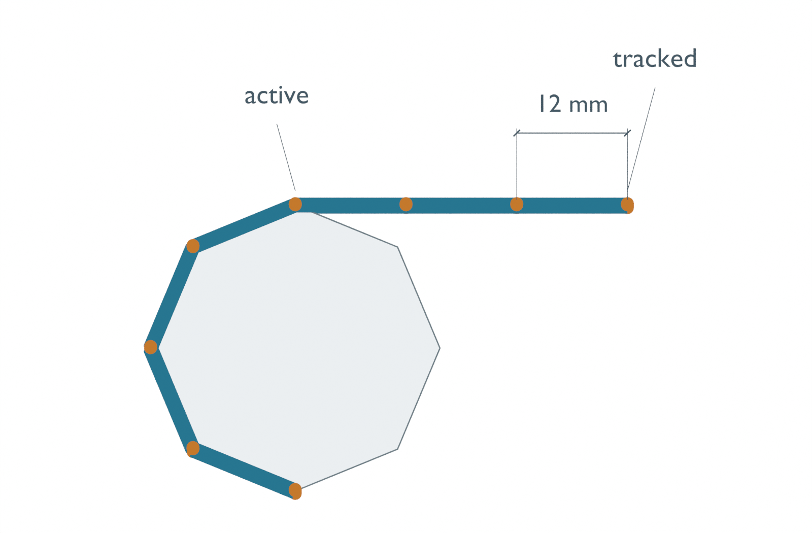
The ideal within-interval calculation gives 113.77–123.14 mm/s for eight teeth and 119.31–120.34 mm/s for 24 teeth. Both advance 24 mm over two tooth intervals. A constant 120 mm/s model therefore gets that total right while flattening the within-interval motion.
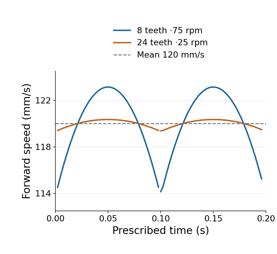
An AI-operated Blender 5.2.2 LTS study on October 5, 2026 retained 99 prescribed samples per case: 198 actual evaluated poses. An independent audit checked the finite polygon, every pin and link’s vertices, persistent identities, end-center distances and the exported positions/times. Actual readback agreed with the 24 mm advance to the displayed precision. Sampled central-difference estimates ranged about 114.15–123.14 and 119.36–120.34 mm/s. They confirm the sampled trend while omitting endpoint/handoff neighborhoods; they are not measurements of the analytic instantaneous extrema above.
The calculated peak-to-trough difference divided by the maximum speed is about 7.61% and 0.86%. Those are not percentage deviations above and below the mean. More teeth also require a larger pitch radius at this fixed pitch—15.68 mm versus 45.97 mm—so this comparison is not a tooth-count recommendation for a physical assembly.
Keep the links connected when the active pin changes
The pitch radius comes from a chord, not a circumference. With pitch p and z teeth, use R = p / (2 × sin(π/z)). The arc-based radius p × z / (2π) would place adjacent polygon vertices only 11.69 mm apart in the eight-tooth case. Drawing 12 mm links onto that polygon introduces a geometry error before any speed calculation.
As the sprocket turns, one pin leaves the polygon for the straight span and its neighbor becomes the active departure vertex. The model keeps the same material pin identities through this handoff. Adjacent centers remain 12 mm apart; the picture is not rebuilt as a newly numbered strip. The link blocks do not stretch to bridge an inconsistent pitch.
The construction has an explicit limit. The span’s height changes by about 1.19 mm for eight teeth and 0.39 mm for 24 teeth. At handoff, position and horizontal speed stay continuous, while the direction of vertical velocity reverses abruptly. This geometric cusp is not a solved impact, friction or chain-force event. A fixed-height guide, compliant chain or physical engagement constraint needs a different model; smoothing the cusp would conceal that missing work.
The native scene stores each sampled pose with constant keyframe holds. Its frame intervals are not uniform physical time near the extra handoff samples, and between-frame playback is a staircase. The graph uses exported prescribed times and coordinates, not animation-frame playback as a speed measurement.
The following executed standard-library Python reproduces the ideal speed limits and height excursion. It does not solve chain contact. mean_speed is the prescribed horizontal throughput, and the extrema are calculated from the ideal chord construction.
from math import pi, sin, cos

pitch, mean_speed = 12.0, 120.0  # synthetic mm and mm/s
for teeth in (8, 24):
    half_angle = pi / teeth
    radius = pitch / (2 * sin(half_angle))
    omega = mean_speed * 2 * half_angle / pitch  # rad/s
    maximum = radius * omega
    minimum = maximum * cos(half_angle)
    ripple = 100 * (maximum - minimum) / maximum
    rise = radius * (1 - cos(half_angle))
    # One tooth interval: horizontal travel is exactly one chain pitch.
    travel = 2 * radius * sin(half_angle)
    assert abs(travel - pitch) < 1e-12
    print(f"{teeth} teeth: {omega * 60 / (2*pi):.3f} rpm; "
          f"speed {minimum:.3f}..{maximum:.3f} mm/s; "
          f"ripple/max {ripple:.3f}%; rise {rise:.3f} mm")
For an average-throughput model, constant pitch advance may be enough. To resolve transport inside a tooth interval, retain discrete pitch geometry and the engagement transition. This differs from the circular tangent geometry in open and crossed belt routing. Neither model establishes contact forces, vibration, wear, positioning accuracy or usable operating speed; no physical chain was tested here.