Before copying an inertia tensor into a robot model, identify both the point it is calculated about and the axes used for its components. A tensor about the center of mass is not the tensor about an offset link origin. Changing the orientation of the axes can also change the numbers, even when the object and its mass distribution stay the same.
An AI-operated Blender 5.2.2 LTS study on October 5, 2026 read finite mesh coordinates for three placements of the same two cuboids. An independent closed-surface integration checked their mass properties against the box-edge calculation. Masses are assigned synthetic inputs. No dynamics solver, hardware measurement or model importer was tested.
The SDFormat 1.12 link specification makes the distinction explicit: the inertial pose locates and orients the center-of-mass frame, and the inertia entries describe moments about that center in those axes. Its off-diagonal convention uses negative mixed mass moments. Those definitions explain why a plausible-looking matrix from a different reference point or orientation is not interchangeable with the requested one.
One arrangement, two different points
Take a 1.2 kg cuboid measuring 240 × 40 × 30 mm, centered at (−40, 0, 0) mm. Add a 0.8 kg cuboid measuring 60 × 80 × 50 mm, centered at (80, 40, 60) mm and turned 30° about Z. Density is uniform within each component and differs between them. These are assigned synthetic masses; the separated parts form an ideal prescribed rigid arrangement with no connector mass.
Its total mass is 2 kg and its mass-weighted center is (8, 16, 24) mm. That is not the midpoint between the component centers. The calculation also retains each cuboid’s finite size: replacing both components with point masses would discard their own central inertia.
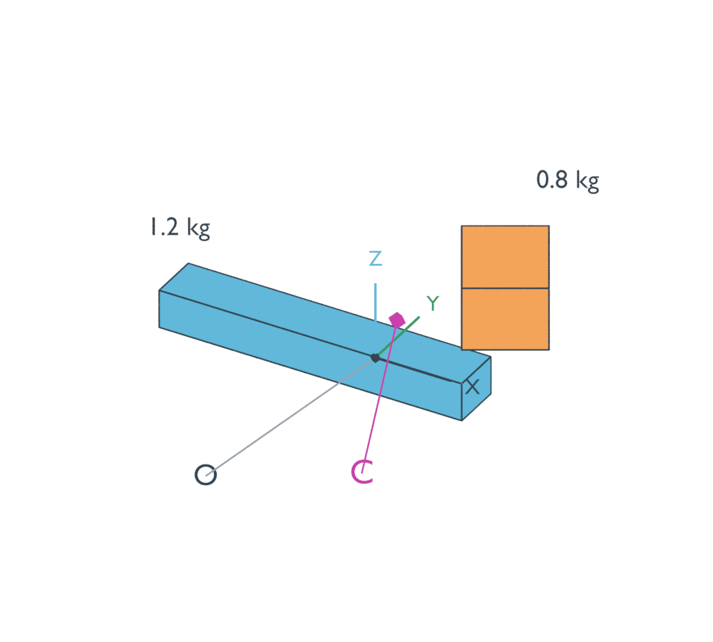
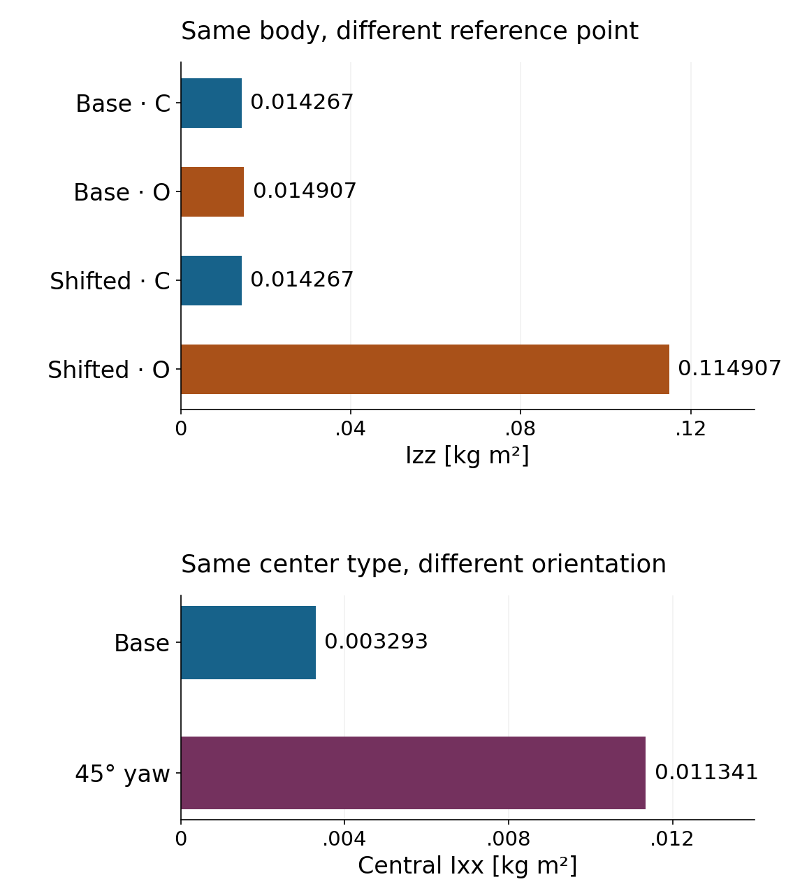
In the unchanged XYZ directions, the assembly’s central Izz is 0.014267 kg m². About the chosen origin O, Izz is 0.014907 kg m². The extra term is 2 × (0.008² + 0.016²) = 0.000640 kg m², because distance from the Z axis involves X and Y.
For the full tensor, the shift from the center C to O is:
I_O = I_C + M[(d·d) Identity − d dᵀ]
Here d points from O to C, and both tensors use parallel axes with the same orientation. The sign of d does not change that quadratic term. This expression starts from the center of mass; it is not permission to add an arbitrary displacement term between two arbitrary origins. Nor does it perform an axes rotation.
If a model field asks for central inertia, supplying I_O merely because the inertial pose is offset would include the wrong reference point. Keep the mass-center location and the central tensor’s meaning consistent instead of adding the offset twice.
Moving everything does not change its central inertia
Translate both components by (200, −100, 50) mm. Their relative layout, mass and orientation remain identical. The new center is (208, −84, 74) mm, but central Izz remains 0.014267 kg m² in parallel axes. Izz about the original fixed O rises to 0.114907 kg m².
The large change belongs to the chosen reference point, not to a newly distributed mass. This is a useful debugging distinction when geometry is moved away from an export origin: check whether the reported tensor is central before treating its increased entries as a changed body property.
Now rotate the entire original arrangement 45° about Z, including both centers and both component orientations. In the fixed XYZ directions, central Ixx changes from 0.003293 to 0.011341 kg m². Copying the old matrix would miss that change. Central Izz remains the same for this particular rotation about Z; a single unchanged entry does not establish that the whole matrix is unchanged.
If R maps the original vector components into the destination axes, the tensor in those destination axes is R I Rᵀ, about the same mass center. Define that direction before using R; using a passive frame change reverses which mapping is needed. A spherical or otherwise isotropic tensor can hide an incorrect rotation routine, so an asymmetric two-component example is more revealing than a cube alone.
The following standard-library Python code reproduces the comparison. It uses meters throughout the inertia calculation and converts only the printed center to millimeters.
from math import cos, sin, radians

# Synthetic cuboids: mass kg, full size m, center m, local yaw degrees.
parts = [(1.2, (.24, .04, .03), (-.04, 0, 0), 0),
         (.8, (.06, .08, .05), (.08, .04, .06), 30)]

def rotation(degrees):
    a = radians(degrees)
    return ((cos(a), -sin(a), 0), (sin(a), cos(a), 0), (0, 0, 1))

def multiply_vector(R, v):
    return [sum(R[i][j]*v[j] for j in range(3)) for i in range(3)]

def study(yaw=0, shift=(0, 0, 0)):
    blocks = []
    for mass, size, center, local_yaw in parts:
        q = multiply_vector(rotation(yaw), center)
        q = [q[i]+shift[i] for i in range(3)]
        R = rotation(yaw+local_yaw)
        principal = [mass*sum(size[j]**2 for j in range(3) if j != i)/12
                     for i in range(3)]
        J = [[sum(R[i][k]*principal[k]*R[j][k] for k in range(3))
              for j in range(3)] for i in range(3)]
        blocks.append((mass, q, J))
    M = sum(p[0] for p in blocks)
    C = [sum(m*q[i] for m, q, J in blocks)/M for i in range(3)]
    I = [[0.0]*3 for _ in range(3)]
    for m, q, J in blocks:
        d = [q[i]-C[i] for i in range(3)]
        for i in range(3):
            for j in range(3):
                I[i][j] += J[i][j] + m*((sum(x*x for x in d) if i == j else 0)-d[i]*d[j])
    return C, I, I[2][2]+M*(C[0]**2+C[1]**2)

for name, yaw, shift in (('base', 0, (0, 0, 0)),
                         ('translated', 0, (.2, -.1, .05)),
                         ('rotated45', 45, (0, 0, 0))):
    C, I, origin_zz = study(yaw, shift)
    print(name, 'COM mm:', [round(x*1000, 3) for x in C])
    print('COM Ixx / Izz / origin Izz (kg m^2):',
          *(f'{x:.6f}' for x in (I[0][0], I[2][2], origin_zz)))
assert abs(study()[1][0][0]-study(0, (.2, -.1, .05))[1][0][0]) < 1e-12
assert abs(study()[1][0][0]-study(45)[1][0][0]) > .001
Before transferring these ideas to a model, label the source tensor with its units, reference point and expression axes. A conversion from kg mm² to kg m² requires a factor of 10⁻⁶, not 10⁻³. Retain the full symmetric matrix unless the chosen axes are known to be principal directions; nonzero off-diagonal entries are not automatically mistakes.
The native audit triangulated the complete outward faces into signed tetrahedra and integrated volume, first moments and second moments independently of the producer’s cuboid-edge formulas. It checked all three placements, both full symmetric tensors and the finite mass-center marker against evaluated mesh coordinates. Six decimal places make the numerical comparison reproducible; they do not establish physical accuracy.
Use this reference-point and axes check when preparing the inertial fields discussed in the URDF versus SDFormat model guide. Geometry-based mass properties remain different from identifying a real robot’s dynamics from measured response. This study does not establish material density, missing fastener or cable mass, parser behavior or hardware dynamics.