If a gripper model reduces each fingertip to a force-only point contact, squeezing harder cannot produce a torque about the line joining those two points. Forces at either point have no lever arm around that line. Before tuning grip force, check whether the contact representation can transmit a moment at all: a soft contact patch and an ideal force-only point are different models.
This is a three-dimensional limitation. A planar drawing can hide the missing twist direction. Lynch and Park’s Modern Robotics explanation of force closure distinguishes the two-point spatial case from soft fingertips that develop contact patches. It also cautions that contact geometry alone does not establish what a robot’s actuators can resist.
Find the line before increasing the force
Consider a synthetic block measuring 80 × 60 × 40 mm. Two ideal fingertip apexes touch the opposite x faces at A = (−40, 0, 0) mm and B = (40, 0, 0) mm. Put the moment origin at the block center, on the A–B line. These dimensions are illustrative, not a gripper specification.
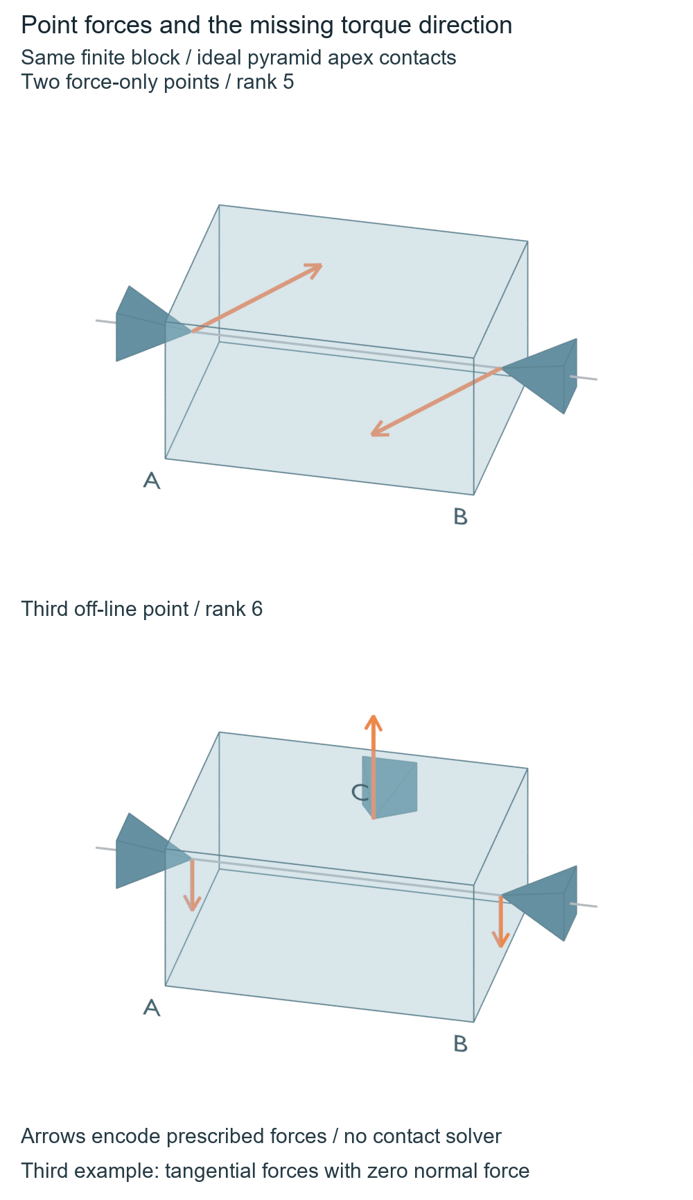
A point force contributes the moment r × f, where r runs from the chosen origin to the contact. At A and B, r has only an x component. Whatever force components you prescribe, the x component of r × f is zero. Higher prescribed force changes the y and z moments in this unrestricted map; it does not add the missing x moment.
For example, forces (2, 1, 1) N and (−2, −1, −1) N sum to zero and produce (0, 0.080, −0.080) N m about the center. They form a couple, but none of it acts about A–B. The unrestricted point-force map has rank five, rather than the six components needed to span spatial force and moment. This is a linear-algebra upper bound, not a friction-limited grasp test.
Turning the entire block and contacts by 37° about the direction (1, 2, 3) changes the world components of that moment to approximately (−0.065, 0.074, −0.054) N m. Its component along the rotated A–B line remains zero. The missing direction follows the grasp; it is not a special property of world x.
These values begin as executed Python calculations for prescribed geometry and vectors. An AI-operated Blender 5.2.2 LTS experiment then constructed three static groups: the original pair, its rigidly rotated and translated copy, and the off-line third-point comparison. Across 20 objects and 82 vertices, an independent audit checked every evaluated world/local vertex, matrix, face, edge, outward normal and CSV row. It reconstructed contact locations and the prescribed forces from the actual arrow endpoints, then independently recomputed moments and map ranks. No contact force, physical slip or object motion was measured.
| Static geometry | Unrestricted map rank | Moment along A–B, N m | Meaning |
|---|---|---|---|
| Original two-point pair | 5 | 0 | Joining-axis moment is missing |
| Rigidly rotated pair | 5 | Approximately 0 | The missing direction rotates with the pair |
| Off-line third point | 6 | 0.060 | Full linear rank; prescribed forces still violate friction |
The rotated geometry gave a small numerical axis residual of 1.16 × 10⁻⁸ N m, and the third example read back as 0.059999997 N m. These are reconstructed results from stored geometric arrows, not torque measurements. The audit used explicit numerical comparison allowances; it does not establish physical accuracy or a minimum torque capacity. A separate control showed that moving the moment origin away from A–B can introduce an apparent axis component when net force is nonzero. Keep the reference point on the contact line for this particular zero-axis argument.
A third point fixes the rank, not the grasp
Add C at (0, 30, 0) mm on the upper y face. Prescribing −1 N in z at each side contact and +2 N in z at C gives zero net force and a 0.060 N m moment about x. The noncollinear third point raises the unrestricted map to rank six.
There is a deliberate catch: these three forces are purely tangential to their respective faces. Each has zero inward normal component. Under the Coulomb contact model described in Modern Robotics, a nonzero tangential force cannot be supported by zero normal force with a finite friction coefficient. The algebraic example therefore does not establish a usable three-contact grasp. Rank, admissible force directions and available force magnitudes answer different questions.
The following standard-library Python reproduces the two moments and exposes that catch. Positions are in metres; its force vectors are inputs, not sensor readings.
from math import sqrt

def cross(a, b):
    return (a[1]*b[2]-a[2]*b[1],
            a[2]*b[0]-a[0]*b[2],
            a[0]*b[1]-a[1]*b[0])

def wrench(points, forces):
    moments = [cross(p, f) for p, f in zip(points, forces)]
    return (tuple(sum(f[i] for f in forces) for i in range(3)),
            tuple(sum(m[i] for m in moments) for i in range(3)))

# Metres, newtons; moments are about the block center.
points = [(-0.04, 0, 0), (0.04, 0, 0)]
forces = [(2, 1, 1), (-2, -1, -1)]
net, moment = wrench(points, forces)
print("pair force N:", net, "moment N m:", moment)
assert abs(moment[0]) < 1e-12
# Every unit-force direction at either point has zero x moment.
for p in points:
    for f in [(1, 0, 0), (0, 1, 0), (0, 0, 1)]:
        assert cross(p, f)[0] == 0

net, moment = wrench(points + [(0, 0.03, 0)],
                     [(0, 0, -1), (0, 0, -1), (0, 0, 2)])
print("third point force N:", net, "moment N m:", moment)
assert abs(moment[0] - 0.06) < 1e-12
# At C the inward normal is -y. This force has no inward part.
inward = 0.0
tangent = sqrt(2.0**2 - inward**2)
print("C inward N:", inward, "tangent N:", tangent)
assert inward == 0 and tangent > 0  # Not feasible for finite mu.
For a simulator diagnosis, first identify what each active contact can transmit. If it supplies only a force at a point, the missing moment is a representation limit; a faster force-control loop cannot create that component. If it supplies a patch moment, inspect that model’s assumptions and parameters instead. Neither the finite geometry nor the calculation here establishes patch torque capacity, force closure, hardware grip strength or resistance to a particular real load. For Drake specifically, the separate geometry-pair and contact-model check explains how to identify a point-contact fallback before interpreting an intended patch. For the broader task, the grasp stability guide connects friction assumptions and contact position to the disturbance envelope. Those checks add context; this experiment does not run Drake or validate a physical gripper.