If a Drake simulation runs but shows point contacts where you expected a contact patch, check the contact model and both collision geometries before changing stiffness. Hydroelastic contact needs suitable representations on both sides, with at least one compliant geometry. The default kHydroelasticWithFallback can keep a scene running by using point contact for unsupported hydroelastic pairs. A running simulation therefore does not establish that the intended patch model is active.
This guide compares the Drake 1.57.0 hydroelastic documentation with that release’s source, checked September 15, 2026. Version 1.57.0 was released September 10. One documentation discrepancy matters for unannotated pairs and is explained below. We did not run a Drake scene or validate a robot’s contact forces.
A rigid body still needs a contact representation
“Rigid body” describes how the body’s motion is modeled. “Rigid-hydroelastic” describes a collision geometry’s contact representation. Giving a robot a rigid link or a collision mesh does not, by itself, make that geometry rigid-hydroelastic.
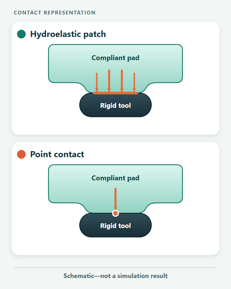
A compliant hydroelastic representation carries an internal pressure field. A rigid representation provides a surface regarded as infinitely stiff. When a compliant gripper pad meets a rigid tool handle, the modeled contact surface lies on the handle; when two compliant geometries meet, it lies where their pressure fields are equal. Drake integrates pressure over the contact surface to obtain a resultant force and moment. Its contact-model explanation describes the approximation.
That distinction matters for grasping: a patch has spatial extent, while point contact summarizes an interaction at a point. Hydroelastic compliance here does not introduce a deformation state for the bodies; it is not a replacement for a deformable-body model. Nor does every patch simulation predict the real grip accurately. The geometry, material approximation and operating conditions still need validation.
Read the pair before tuning the force
Start with the actual collision geometries, not the visual meshes. In the table, C means compliant-hydroelastic, R means rigid-hydroelastic, and U means no hydroelastic representation. These are contact-model classifications, not labels for the physical material.
| Geometry pair | Strict kHydroelastic |
kHydroelasticWithFallback |
|---|---|---|
| C + R, or C + C | Hydroelastic contact when the supported geometries intersect | Hydroelastic contact when the supported geometries intersect |
| R + R | Exception for an unfiltered pair that cannot be culled | Point-contact fallback, where point contact supports the pair |
| C + U, or R + U | Exception for an unfiltered pair that cannot be culled | Point-contact fallback, where supported |
| U + U | Exception in the v1.57.0 source path; see the discrepancy below | Point contact, where supported |
These outcomes follow the release’s pair classifier and strict/fallback dispatch. They apply to eligible collision pairs: filtering, supported shapes and actual intersection still matter. Broad-phase collision checks can raise an unsupported-pair exception before a detailed contact patch is available. A filtered pair is omitted from contact computation; this does not establish that the objects cannot collide physically.
A documentation discrepancy: the v1.57.0 user guide says two geometries without hydroelastic representations are ignored in strict mode. In the same release’s source, the classifier returns kUnsupported when either geometry has an undefined hydroelastic type, and strict dispatch throws on that failed result. Do not rely on U + U being silently ignored. This is a source-code reading, not a reproduced runtime test; check a minimal scene against your installed release if that behavior affects your model.
The fallback column is not an all-errors recovery promise. The fallback query API first attempts a contact surface, then a point pair; it can still throw if the latter cannot be computed. Conversely, selecting kPoint asks for point contact directly: hydroelastic annotations do not override that choice.
Shape-specific restrictions also qualify the first row. For example, v1.57.0’s classifier rejects a compliant half-space against a compliant mesh for hydroelastic contact. Two half-spaces cannot fall back to a finite point-penetration result either. “At least one compliant geometry” is necessary for a patch, but is not the complete shape-support test.
A gripper example that separates two different mistakes
Imagine a compliant pad closing on a rigid tool handle. Both geometries have valid hydroelastic representations, so this is a supported compliant–rigid pairing. There is no need to mark both compliant simply to avoid the word “rigid.”
Now remove the handle’s hydroelastic representation while leaving its collision geometry in place. The pair becomes C + U. Strict mode exposes the missing representation as an exception; fallback may produce a point contact instead. Increasing the pad’s hydroelastic modulus cannot add the missing representation to the handle. That is a configuration problem before it is a parameter-tuning problem.
A different change—declaring both pad and handle rigid-hydroelastic—creates R + R. Both are annotated, but there is still no supported hydroelastic patch between them. Decide which surface should carry the compliance in your model, or deliberately use a supported point-contact model. Do not choose a classification merely because it makes an error disappear.
Drake supports explicit properties in model files or through its API, and also offers SceneGraph default proximity properties. When defaults are configured, a missing XML tag alone does not establish that the geometry is U; inspect the effective properties. Explicit model/API properties take precedence over defaults. The representation setup section explains these routes.
Check what the scene actually computes
Use a small diagnostic scene before changing a full robot model:
- Record the Drake version and selected contact model. Compare with that release’s documentation.
- Identify the two collision geometries and their effective C, R or U classifications. Check filtering and supported shapes alongside the properties.
- Display the collision geometry and contact visualization. In the user guide’s Meldis view, red force arrows accompany hydroelastic contact patches; green arrows indicate point contact. Check that contact surfaces are enabled before treating a hidden patch as absent.
- Change one suspected cause at a time. If fallback was unexpected, fix or deliberately accept that pair’s representation before adjusting stiffness, friction or mesh resolution.
The official hydroelastic basics notebook at v1.57.0 provides a starting example. A useful troubleshooting record contains the version, contact model, geometry names, effective classifications, filtering state and observed patch or point result. That record makes a configuration change interpretable; it is not a force-accuracy benchmark.
If you are still choosing a simulation environment, the robot simulator comparison addresses that broader decision. Once your Drake pair produces the intended contact type, sim-to-real transfer explains the separate problem of matching simulated behavior to hardware. First establish which model computed the contact; then evaluate whether it is a useful model of the task.