Grasp stability is the ability of actual contacts to resist the external forces and moments expected during a task without unacceptable slip, loss or object damage. Finger force alone is not sufficient; contact position, normal direction, friction, center of mass and acceleration determine the wrench margin.
A friction cone describes tangential forces that a contact can support under a Coulomb model. Force closure describes whether the modeled contacts can generate arbitrary small disturbance wrenches. Both depend on assumptions that real pads, objects and sensing can violate.
Use this guide with the robot grasp-planning guide and robot gripper selection guide. Validate planning scores against measured contact and task outcomes.
Start with the disturbance wrench the grasp must resist
A wrench combines force and moment. Gravity contributes a force through the center of mass; acceleration and deceleration add inertial load; cable pull, impacts and contact with the environment add task disturbances. Their direction changes with object and robot pose.
Define mass, center-of-mass uncertainty, acceleration envelope, orientation, shock and required margin. A stable tabletop lift can fail during a fast turn because the required wrench has changed.
Separate routine loads from credible abnormal loads and define the allowed response.
.jpg)
Build a contact model before choosing force
Point contact with friction, soft-finger contact and finite-area contact allow different forces and moments. Pad compliance spreads pressure and changes the effective contact patch. Curved or sharp surfaces can move the contact as force increases.
Estimate contact location, normal, area and pad deformation for the installed fingers. A CAD touch point is not proof of the executed contact.
| Contact factor | Model effect | Physical uncertainty | Required evidence |
|---|---|---|---|
| Normal direction | Cone axis | Pose and surface error | Contact geometry test |
| Friction coefficient | Cone angle | Material, wear, moisture | Slip test range |
| Normal force | Tangential capacity | Drive and pad compliance | Calibrated force |
| Contact location | Moment arm | Finger placement error | Tactile or visual check |
| Contact area | Pressure and torsion | Deformation | Pressure or torque test |
Interpret the friction cone as a bounded model
Under Coulomb friction, tangential force magnitude is bounded by friction coefficient times normal force. The feasible directions form a cone around the contact normal. Larger assumed friction widens the cone, but the coefficient is rarely one exact constant.
Measure or conservatively bound friction for clean, dusty, wet, worn and contaminated surfaces. Static and dynamic friction can differ, and incipient slip can change the interface.
Increase normal force only within damage and actuator limits
Higher normal force can increase tangential capacity, but it also raises object stress, pad deformation, motor current and structural load. Fragile, soft, hollow or surface-finished items may be damaged before the desired margin is reached.
Create lower and upper force bounds from slip and damage tests. Account for force-control error, transmission friction and thermal limits rather than relying on command value.
Use contact position to create useful moment arms
The same contact force produces different moments about the center of mass depending on contact location. Contacts clustered on one side can resist translation but have little torsional authority. A center-of-mass offset increases required finger wrench.
Plan opposing contacts and approach direction from object geometry and task loads. Verify realized finger placement after closure.
Distinguish force closure from guaranteed success
Force closure means the idealized contacts can balance arbitrary small wrenches under the assumed contact model and friction. The Modern Robotics force-closure resource explains the wrench-space condition.
It does not guarantee adequate force magnitude, collision-free fingers, reachable approach, robust control, unmodeled compliance or survival under large shocks. Treat it as one planning condition.
| Claim | What it supports | What remains unproven | Validation |
|---|---|---|---|
| Antipodal geometry | Opposed contact potential | Actual contact and friction | Placement test |
| Force closure | Local wrench directions | Magnitude and damage | Wrench-margin test |
| High normal force | More tangential capacity | Object integrity | Slip-damage sweep |
| Tactile no-slip | Current contact state | Future shock margin | Dynamic transport |
| Static lift success | Gravity at one pose | Acceleration envelope | Trajectory replay |
Model soft fingers and area contact intentionally
A compliant pad can support torsional moment and conform to irregular surfaces, but its behavior depends on pressure distribution, material, thickness and deformation rate. A point-contact model may understate or overstate capability.
Measure torsional slip, hysteresis and recovery across force and temperature. Replace the model only when data supports the additional parameters.
Detect incipient slip close to the contact
Local tactile sensing can observe pressure redistribution, shear or vibration before gross object motion. The robot tactile-sensor guide covers local contact evidence. Wrist force-torque sensing measures net load but can miss which finger is slipping.
Motor current and vision add indirect evidence with different delays. Fuse signals by timestamp and failure mode rather than averaging unrelated scores.
Connect planning score to execution feedback
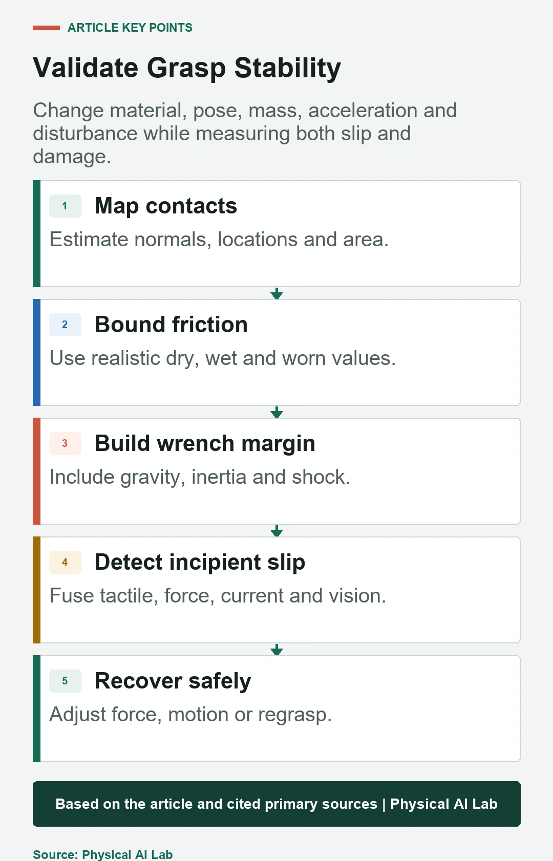
A planner may rank grasps by force closure, epsilon quality, clearance, reachability or learned success. Store the assumptions and predicted margin with the selected grasp. After closure, compare actual contact, force and slip evidence to the plan.
If execution differs, adjust force, slow motion, reposition or regrasp. Do not keep increasing force after contact geometry has failed.
Control transport acceleration within the grasp envelope
Robot trajectory creates the load that the grasp must carry. Limit linear and angular acceleration and jerk based on object mass, center of mass and measured margin. Tool reorientation changes gravity relative to contacts.
Test emergency and protective stops as well as nominal motion. A stop can produce the largest transient wrench in the mission.
Validate slip and damage boundaries together
Sweep material, surface condition, contact pose, object mass, center of mass, normal force, acceleration, rotation and disturbances. Measure slip onset, drop, deformation, marking, peak force and recovery success. Include worn pads and placement error.
The NIST robotic grasping program illustrates the broader need for performance measurement in manipulation. Use task-specific artifacts and ground truth.
Operate with contact state and bounded recovery
Log planned contacts, realized pose, commanded and estimated force, tactile state, wrist wrench, slip alarms, motion and regrasp history. Define how the robot lowers, places or contains an object after confidence drops.
Release with a concise checklist.
- Define the full disturbance-wrench envelope.
- Bound friction and contact geometry from tests.
- Balance slip margin against object damage.
- Monitor actual contact and incipient slip.
- Validate transport, stops and recovery with worn hardware.
Frequently asked questions
What determines a friction cone angle?
Under the Coulomb model it depends on friction coefficient, which must be bounded for the actual material and condition.
Does force closure mean an object can never drop?
No. It is a model condition; force limits, errors, damage, large disturbances and control still matter.
Can stronger grip prevent every slip?
No. It can damage the object, saturate the actuator or fail when contact geometry is poor.
Can stability be monitored without tactile sensors?
Partly with force, current and vision, but they observe different and often less local slip evidence.
Why can a static lift pass but transport fail?
Acceleration, rotation, stops and impacts create additional forces and moments beyond static gravity.
Model Margin and Physical Contact Boundary
Force-closure and friction-cone calculations are model evidence, not a safety guarantee. Validate actual contacts, object integrity and recovery across the mission envelope.