A joint can stay inside its sampled path tolerance and still miss its goal tolerance. The reverse is more subtle: a later endpoint cannot rescue an earlier path violation because the examined Joint Trajectory Controller source takes the active path-abort branch first. Our four Blender slider cases made these outcomes easy to distinguish, but they also exposed an important limit: three static positions cannot prove what happened continuously between them.
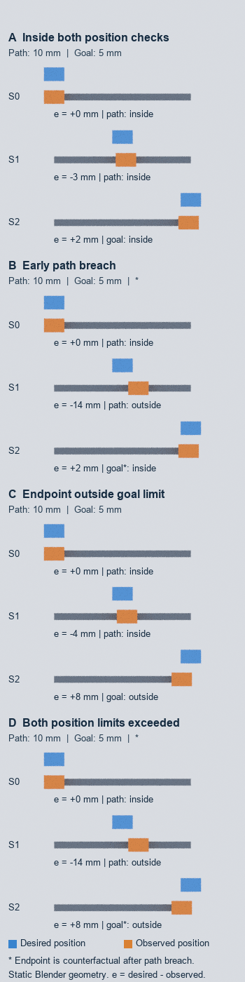
Each static lane represents the same prismatic joint coordinate, with desired positions of 0, 60, and 120 mm. Only indices 0 and 1 were path checks, with a 10 mm tolerance. Only index 2 was the endpoint goal check, with a 5 mm tolerance. That separation matters. Applying both tolerances to every sample would create classifications that the experiment was not designed to support.
The four cases separate the two questions
Each case used the same finite rail and blue desired carriage. The orange observed carriage changed position. We recovered both positions from the centroids of their evaluated mesh vertices and projected them onto the measured rail axis rather than reading object-location fields as the answer.
| Case | Observed positions | Largest path error at indices 0–1 | Goal error at index 2 | Correct reading |
|---|---|---|---|---|
| Control | 0 / 63 / 118 mm | 3 mm | 2 mm | Both sampled path checks and the endpoint check are inside their thresholds. |
| Early path breach | 0 / 74 / 118 mm | 14 mm | 2 mm | The middle sample is outside path tolerance; the later endpoint is counterfactual for an actual controller run. |
| Goal only | 0 / 64 / 112 mm | 4 mm | 8 mm | The sampled path positions are inside 10 mm, but the endpoint is outside 5 mm. |
| Both | 0 / 74 / 112 mm | 14 mm | 8 mm | The middle path check is outside first; the endpoint comparison is again counterfactual. |
We used an authored 8-micrometre allowance for floating-point geometry readback, not a claim about robot measurement accuracy. Each full error interval remained on one side of its threshold, so the rounded millimetre classifications stayed unambiguous. In the examined positive-tolerance predicate, absolute error must exceed the threshold to violate it; equality is allowed. None of our four cases depended on equality.
Why the 118 mm endpoint does not clear an earlier breach
The official FollowJointTrajectory action definition distinguishes path tolerances during execution from goal tolerances at the final state. The examined ros2_controllers implementation also separates the phase checks: state/path checking occurs before the last point, and the active action’s path-violation abort branch precedes the alternative endpoint branch.
That branch order changes how to describe the Early path breach case. Its observed midpoint was 74 mm against a 60 mm target, so the 14 mm error exceeded the 10 mm path threshold. We still rendered an observed endpoint at 118 mm to compare the two predicates, but an actual execution following the examined branch would already have aborted. Saying that this case “eventually passed the goal” would turn an explanatory counterfactual into a false runtime claim.
The Both case has the same issue. Its 112 mm endpoint is 8 mm from the 120 mm target, but the 14 mm middle error is encountered first. When diagnosing a real action, stop treating samples after a path abort as executed controller states unless the trace proves they occurred.
An endpoint outside 5 mm is not yet a timeout
The Goal only case answers a different question. Its path samples had errors of 0 and 4 mm, both inside the authored 10 mm path tolerance. Its endpoint error was 8 mm, outside the 5 mm goal tolerance. This is the clean example of a sampled path check that looks acceptable while the endpoint position check does not.
It still does not prove a goal-time violation. The action interface allows extra time for the final state, and the examined controller source checks goal-state error together with the applicable time condition. Our Blender scene had no controller clock, settling period, or later feedback sample. The defensible conclusion is “outside the endpoint position tolerance at this static sample,” not “the action timed out.”
This is also why one generic tracking_error summary is inadequate. A useful log should identify the joint, the phase, the desired and observed values, the effective tolerance, and the timestamp. For prismatic joints, the official JointTolerance message documents position in metres. Revolute-joint tolerances use angular units, so the numeric thresholds in this slider experiment should not be copied into a rotary joint configuration.
A practical tolerance-debugging sequence
- Identify the phase first. Determine whether the error came from an active path check or the endpoint goal check.
- Use the effective tolerance for that joint and field. Position, velocity, and acceleration tolerances are separate. This experiment measured position only.
- Preserve branch order. Once an actual path violation aborts the goal, later planned positions are not evidence of execution.
- Keep goal error and goal time separate. An endpoint outside tolerance needs clock and allowance evidence before it becomes a deadline conclusion.
- Match the sampling claim to the data. Three checked positions say nothing about unobserved errors between them.
The last point connects this experiment to trajectory joins: matching an endpoint does not establish the behavior between endpoints. It also shows why a static scene is narrower than a simulation fidelity acceptance test, which would need controller timing and runtime behavior rather than geometry alone.
We rendered and reloaded the owned Blender scene successfully, and the geometry audit recovered all twelve pairs of desired and observed coordinates. The controller code linked here is a pinned development revision, rather than a claim about an installed controller or a released version. We did not run ROS 2, ros2_control, Joint Trajectory Controller, interpolation, velocity or acceleration checks, robot dynamics, collision, hardware, or safety logic. The result is a focused visual test of two position predicates: path error at the first two samples and goal error at the final sample.