A pawl that looks close to a ratchet tooth may still be more than 4 mm away, while another pose that looks similarly close may place the two solids inside each other. I found both outcomes in one controlled Blender comparison. Across six static layouts, four wheel-and-pawl pairs were separated. The two layouts at a 10-degree wheel phase had positive-volume intersection at both tested pawl stops.
That result changed the useful question. I could not choose a stop angle by looking for the smallest apparent tip gap. I had to separate wheel phase from pawl stop, classify the full finite solids, and identify which real polygon features supplied a distance witness. The experiment does not show a working ratchet. It shows why a nearby tip is insufficient evidence of tooth engagement.
I built and measured the model in an AI-operated Blender 5.2.2 LTS session on October 8, 2026. The six cases were independently authored static poses. No wheel rotation, spring return, pawl drop, contact force, or hardware action was simulated.
The same stop angle did not give the same relation
The wheel is a generic asymmetric 12-tooth solid, 6 mm thick. Each 30-degree pitch places a root at radius 32 mm and a tip at radius 40 mm, with the tip shifted 8 degrees from its corresponding root. The root-to-tip flank spans 8 degrees of wheel phase; the tip-to-next-root flank spans the remaining 22 degrees. “Short rising flank” and “long falling flank” are geometric labels in this model; they do not establish a drive flank, locking flank, or load path.
The pawl is another generic closed solid, also 6 mm thick. It extends 22 mm from a mathematical pivot at [0, 58, 0] mm. Its pivot end is 8 mm wide and its tip face is 2 mm wide. The pivot is a reference point, not a modeled pin, bearing, stop, or spring attachment.
With the wheel centre at [0, 0, 0] mm, I compared wheel phases of 0, 10, and 20 degrees about positive Z. Each phase was paired with pawl stop angles of 15 and 25 degrees, measured counterclockwise about Z from the pawl’s initial local negative-Y direction. Both solids had the same local Z centre; the separate display rows added no physical layer offset. The resulting six cells changed only those two inputs while preserving the same wheel and pawl dimensions.
The measurements did not form a simple “larger stop means smaller gap” pattern. At a 0-degree wheel phase, the 15-degree stop was separated by 2.601–2.602 mm and the 25-degree stop by 2.641–2.642 mm. Both nearest wheel witnesses lay on a long falling flank. At a 20-degree phase, the 15-degree stop was separated by 1.452–1.453 mm near a short rising flank, while the 25-degree stop was separated by 4.617–4.618 mm near an exact tooth tip.
At the 10-degree phase, both stops produced positive solid intersection. There is therefore no positive clearance to report for those two rows. I also do not report an intersection volume or penetration depth: the experiment established finite interior overlap, but those additional quantities were outside its measurement contract.
Six finite-solid checks, not one visual gap
| Wheel phase | Pawl stop | Finite-solid result | Finite feature / interior-point context | Measured result |
|---|---|---|---|---|
| 0° | 15° | Disjoint | Wheel long falling flank | 2.601–2.602 mm separation |
| 0° | 25° | Disjoint | Wheel long falling flank | 2.641–2.642 mm separation |
| 10° | 15° | Positive-volume intersection | Long falling flank + pawl tip-face context | No positive clearance; volume and depth not measured |
| 10° | 25° | Positive-volume intersection | Short rising flank + pawl left-taper context | No positive clearance; volume and depth not measured |
| 20° | 15° | Disjoint | Wheel short rising flank | 1.452–1.453 mm separation |
| 20° | 25° | Disjoint | Exact wheel tooth tip | 4.617–4.618 mm separation |
The feature descriptions in the two intersecting rows need care. They identify the nearest side features around an independently verified interior point. They are not contact witnesses, seated faces, or evidence that a particular flank would carry load. Once two solids overlap, the phrase “nearest flank” can easily sound more mechanical than the data supports.
For the four disjoint rows, the intervals are outward-rounded bounds from the evaluated finite geometry. They are not exact minima. The model used a 4-micrometre coordinate allowance and an 8-micrometre two-solid comparison allowance. Those values describe numerical consistency in this authored dataset, not manufacturing tolerance, measuring-instrument accuracy, backlash, or a recommended physical clearance.
Why the full finite faces changed the answer
A centerline sketch cannot classify these cases. A ray from the pawl pivot may cross the wheel outline while the pawl body remains outside it. The pawl tip point may sit near a tooth tip even when their finite faces point past one another. A nearest-vertex test may miss a shorter edge-to-edge or edge-to-face witness. Extending a tooth edge into an infinite line can also invent a closest point beyond the actual segment.
I therefore treated each part as a filled, extruded polygon. The wheel contributed 92 actual finite triangles and the pawl 12 in each case. Across all six cells, the experiment measured 12 unshared closed meshes and 336 evaluated vertices. Three complete reads, plus a distinct representative read, checked the same authored and evaluated geometry.
For a separated pair, the actual cap triangles established the filled polygon profiles, including the wheel’s concave tooth spaces. Comparing all finite profile edges supplied a global XY lower bound. Barycentric points on actual finite side triangles supplied a 3D upper bound within their common thickness range. The calculation included a 10-nanometre arithmetic allowance and rounded the reader’s lower endpoint downward and upper endpoint upward. These are bounds from the actual model coordinates, not an exact minimum or a physical measurement. For the two intersecting pairs, a point independently shown to be inside both finite solids established positive-volume intersection. Its distance to surrounding boundaries was useful as a proof margin, but it was not converted into penetration depth.
This approach matters because the wheel outline is asymmetric. At 0 degrees, both stop settings happened to be nearest to a long falling flank, yet their gaps differed. At 20 degrees, the governing wheel feature switched between a short rising flank and an exact tooth tip, and the 25-degree setting produced the larger separation. Stop angle alone did not order the outcomes.
Blender’s Circle primitive documentation was checked on October 8, 2026 and supports only the modeling vocabulary used here: a circle can be represented as a flat polygon with a chosen vertex count, radius, and fill. The experiment authored its asymmetric 24-point wheel outline directly. The documentation does not define a ratchet profile or validate one-way operation.
Phase and stop are different design controls
The most useful finding is not that one of the two stops was “better.” Neither setting stayed separated across the sampled phases, and neither was proven functional. At 10 degrees both intersected. At 0 degrees both were separated by roughly 2.6 mm. At 20 degrees the 15-degree stop came closer than the 25-degree stop by more than 3 mm.
That means a stop adjustment should be checked against the intended wheel-phase range. If a designer changes only the pawl stop, the correction may improve one sampled phase and worsen another. If the governing feature changes from a flank to a tooth tip, the next useful modification may be pivot placement, pawl taper, tip width, or tooth geometry rather than another stop increment.
The result also differs from the cam base-radius and roller pressure-angle experiment. That problem asks how cam geometry changes a roller-follower pressure-angle decision. Here the problem is a finite wheel-and-pawl relation at separately controlled phase and stop angles.
It also differs from the gearbox backlash experiment, which compares different approach histories at the same input angle. These ratchet cells have no history. Each pose was authored independently, so the measurements cannot say that one state physically transitions into the next.
A static intersection is not a working ratchet
The experiment did not include a spring to press the pawl toward the wheel, gravity, a contact solver, friction, or continuous rotation. It did not test whether the pawl climbs a tooth, drops into a space, blocks reverse rotation, or survives repeated loading. There was no physical pin, bearing, housing, axial retainer, lubricant, tolerance stack, or manufactured part.
Positive-volume intersection should therefore be read as an impossible shared-space condition in this static geometry, not as measured force, stress, wear, damage, or a preferred seated state. Conversely, a positive gap does not prove that the pawl will engage later in the cycle. A separated static pose may be intentional approach clearance, excessive clearance, or simply a phase that the mechanism passes through.
The six samples do not certify a continuous angular range. An unmeasured phase between 0 and 10 degrees could change the finite relation, and the same is true between 10 and 20 degrees. The experiment says nothing about the first angle of contact or about contact persistence. Those questions need denser, independently checked samples or an actual continuous collision analysis.
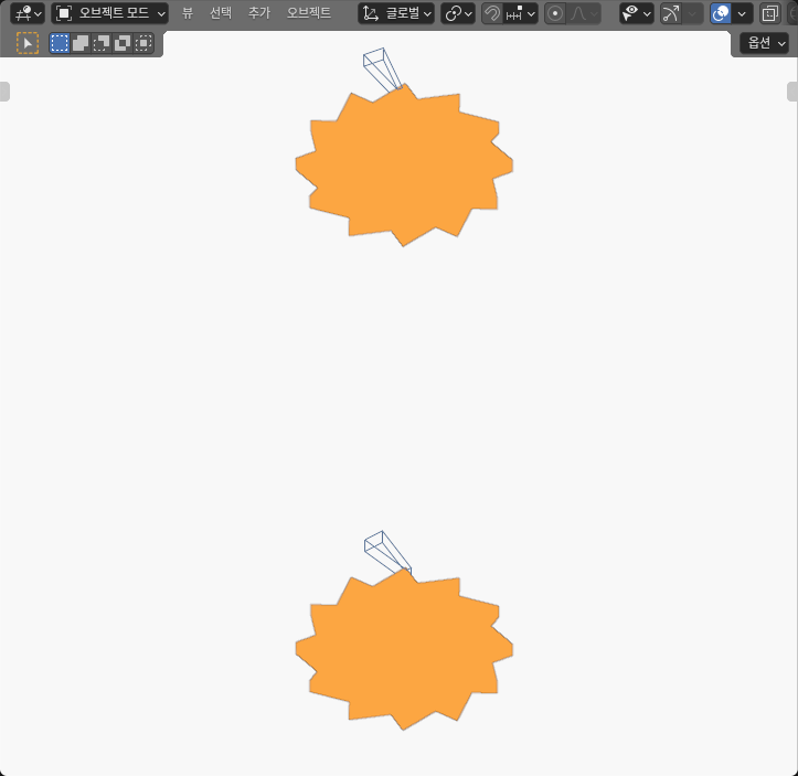
The screenshot has similar limits. It shows the two 10-degree layouts clearly, but an opaque wheel can occlude a wire pawl. A pixel overlap does not establish interior overlap, and a missing visible tip does not establish absence. The classification and distances come from the evaluated mesh geometry, not from the captured image.
How I would use the result in a redesign
I would begin by choosing the wheel phases that matter for the intended mechanical cycle, then repeat the finite check at those exact phases. At every phase, I would compare several stop settings and keep the governing feature pair with the distance or intersection result. That produces a map of why a stop succeeds or fails instead of one attractive screenshot.
If a shallow stop is separated and a deeper stop intersects at the same phase, I would add intermediate authored stops to bracket the change. If both stops are separated, I would inspect face normals before deciding which direction to move. If the nearest wheel feature switches between a flank and a tip, I would test the pivot or pawl shape as a separate controlled variable. Any geometry revision should be rerun across all selected phases because one local correction can create another conflict.
The direct answer from this six-case experiment is simple: proximity at the pawl tip did not predict finite tooth engagement. Wheel phase and stop angle had to be checked independently, and the full closed solids—not centerlines, infinite edge extensions, or screenshot pixels—decided whether each sampled state was separated or intersecting.