A bearing ring can have nominal radial clearance on the shaft and still fail to reach the shoulder. In my Blender comparison, every case kept the same 0.1 mm radial difference between the 8.1 mm ring bore and the 8.0 mm shaft seat. At the authored seated positions, however, the 0.3 and 0.6 mm fillets lay at the intended contact boundary, while the 1.5 mm fillet occupied positive volume inside the ring. Moving the ring 0.75 mm axially made all three pairs separate, but that also moved the ring away from shoulder support. Bore fit, fillet clearance, and shoulder seating are therefore three different checks.
This was an AI-operated Blender 5.2.2 LTS experiment with six independently authored static poses. It used generic faceted shaft and annular-ring solids, not actual bearing parts or vendor CAD. It did not simulate assembly, force, preload, stress, friction, life, or hardware performance.
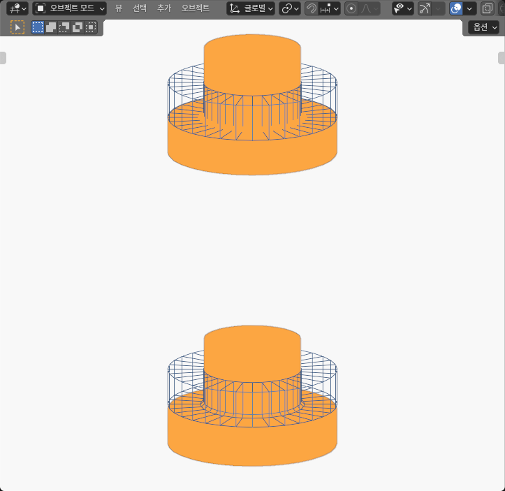
Bore clearance did not answer the shoulder question
The nominal shaft seat radius was 8.0 mm. The ring’s smallest bore radius was 8.1 mm, leaving a 0.1 mm radial difference in every condition. A bore-only check would therefore return the same answer for the small, medium, and large fillets.
The shoulder region changed that answer. Each shaft profile rose from the 8.0 mm seat into a larger shoulder through a 0.3, 0.6, or 1.5 mm authored fillet. The ring was 6 mm wide with a 14 mm outer radius. Its lower bore edge opened from an 8.1 mm radius to an 8.6 mm radius through a 0.5 mm axial, 45-degree chamfer. The shaft shoulder also had a 14 mm radius, with its bottom 6 mm below the shoulder and journal top 12 mm above it. These are authored model dimensions, not a bearing catalog specification. At the nominal axial position, its shoulder face was intended to sit at Z = 0.
That geometry creates two independent questions. First, can the bore pass over the cylindrical seat? Second, can the ring face reach the shoulder without the inner edge occupying the shaft transition? The first check stayed unchanged. The second depended on the fillet.
SKF’s bearing maintenance handbook was checked on October 8, 2026, at PDF page 42 (printed page 38). It explains the broader design context: bearing rings need adequate support at adjoining shoulders, and a larger shaft transition radius may require a suitable relieved spacing collar in some loaded arrangements. I used that only as motivation for separating shoulder support from transition clearance. I did not transfer catalog dimensions, test a spacing collar, or infer a load or strength recommendation from the handbook.
The broader robot joint bearing selection guide covers load paths, preload, housing stiffness, shoulder squareness, and complete-joint qualification. This experiment isolates one narrower geometric failure that must be resolved before those assembled-system checks can be meaningful.
Six static poses exposed three different relations
Each fillet family had two separate static cells. The nominal cell placed the ring at the shoulder plane. The relief cell translated the same ring by +0.75 mm along the common axis. No ring was animated between those positions.
| Fillet radius | Ring position | Actual finite relation | Conservative distance interval | What the sample establishes |
|---|---|---|---|---|
| 0.3 mm | Nominal, Z = 0 |
Boundary or numerical band | Not a positive clearance | Intended shoulder-plane contact; no disjoint gap proved |
| 0.3 mm | Relief, Z = +0.75 mm |
Disjoint | 0.091-0.100 mm | Transition clears, while the ring is axially off the shoulder |
| 0.6 mm | Nominal, Z = 0 |
Boundary or numerical band | Not a positive clearance | Intended shoulder-plane contact; no disjoint gap proved |
| 0.6 mm | Relief, Z = +0.75 mm |
Disjoint | 0.091-0.100 mm | Transition clears, while the ring is axially off the shoulder |
| 1.5 mm | Nominal, Z = 0 |
Positive-volume intersection | Not reported as a distance or depth | The large transition occupies interior volume of the ring |
| 1.5 mm | Relief, Z = +0.75 mm |
Disjoint | 0.068-0.077 mm | The sampled offset separates the solids but removes shoulder-face contact |
The 0.3 and 0.6 mm nominal cases were deliberately classified as boundary or numerical band, not as clear gaps. Independent finite witnesses lay on both shoulder boundaries within sub-nanometre arithmetic residuals. That supports the intended face-contact interpretation without pretending the model proves a positive clearance.
The 1.5 mm nominal case was different. An independently checked point lay inside both closed triangular solids with more than 8 micrometres of margin to every finite boundary. This proves that a genuine interior intersection existed in the actual evaluated geometry. I do not report an exact intersection volume because the audit did not establish one from the native meshes. The result is also not a penetration depth, assembly force, or damage estimate.
All three relief cells were disjoint. Their distances were certified as intervals rather than exact minima. The table rounds the calculated bounds outward. The large-fillet offset left a smaller separation interval than the two smaller fillets, even though every ring had the same 0.75 mm axial translation. That is why the axial offset alone is not a substitute for checking the nearby transition geometry.
Relief removed overlap but also removed shoulder contact
The relief result is easy to misread. Moving the ring 0.75 mm away from the shoulder resolved the measured solid relation in all three cases. It did not produce a validated bearing seat.
A bearing inner ring normally needs a defined axial support condition. In this model, the relieved ring was no longer on the shoulder plane. The remaining 0.068-0.100 mm geometric separations describe the nearest certified shaft-ring surface distances in those sampled poses. They do not say that the ring is supported, that the offset is the minimum required relief, or that a manufactured collar with that spacing would be adequate.
That distinction changes the design decision. If the nominal large-fillet pose intersects, do not simply move the ring until the overlap disappears and call the installation solved. The next design has to provide both transition clearance and an intentional support face. Depending on the real assembly, that could mean a shaft shoulder detail compatible with the ring chamfer, a properly designed relieved component, or a different bearing and mounting geometry. Each choice needs its own dimensions and load checks.
The same reasoning applies to smaller fillets. Their nominal samples reached the intended boundary in this model, but a boundary classification is not a manufacturing tolerance. Real parts still need the bearing manufacturer’s permitted abutment dimensions, actual corner radii or chamfers, shoulder squareness, surface finish, fits, and installation requirements.
The model checked finite solids, not ideal circles
Each shaft was a closed revolved mesh built from a 22-point radius-height profile. The fillet followed a quarter-circle profile from the shoulder plane to the cylindrical journal, represented by 16 straight profile segments, and the revolution used 32 azimuth segments plus two axis poles, producing 642 evaluated vertices per shaft. Each ring used five radial-height loops with 32 samples, producing a closed 160-vertex annular solid. Across six cells, the experiment checked 12 independent meshes and 4,812 evaluated vertices.
This construction matters because neither a centerline nor a bounding box can answer the seating question. Filling the annular bore would invent material inside the ring. Checking only the 8.0 and 8.1 mm radii would miss the shoulder transition. The audit instead retained the bore, reconstructed the full shaft and ring surfaces, checked outward topology and finite triangle witnesses, and repeated complete geometry reads three times plus a separate representative check.
The authored coordinate allowance was 4 micrometres, the two-solid comparison allowance was 8 micrometres, and the arithmetic reserve was 10 nanometres. These are numerical consistency rules for this model. They are not manufacturing accuracy, metrology capability, bearing clearance class, or an acceptable fit tolerance. The 32-sided revolution is also an explicit faceted model, not a claim of equivalence to a perfectly smooth machined circle.
The static cells leave several questions open. They do not show whether a ring can travel continuously to the seated pose, whether thermal or press-fit deformation changes the relation, or whether a real chamfer meets a real shaft radius. They also omit raceways, rolling elements, seals, retention features, tools, and nearby components. For a related example of why face contact needs a separate check from nominal length, see the blind-hole screw seating experiment.
Make support and transition clearance separate acceptance checks
For a real design review, begin with the exact shaft-seat diameter, shoulder diameter, transition definition, ring bore, ring chamfer or corner radius, and the axial support face. Model the shaft transition and ring edge as finite profiles rather than replacing them with nominal cylinders. Then evaluate at least these conditions separately:
- The cylindrical seat and bore have the intended fit or clearance.
- The ring can reach the intended support face without entering the shaft transition.
- Any relief or collar clears the transition while still providing the required ring support.
- The full mounting stack meets the manufacturer’s dimensional, load, fit, and installation requirements.
If the nominal seated geometry intersects, change one controlled feature and repeat both the clearance and support checks. Reducing a fillet, increasing a ring chamfer, or adding a relieved support component may alter stress, strength, support area, and installation requirements, so a geometry-only pass cannot rank those options.
The useful conclusion from these six Blender poses is narrow. A 0.1 mm nominal radial bore difference did not determine whether the ring could seat at the shoulder. The small and medium fillets reached the intended contact boundary; the large fillet produced a verified finite overlap. Axial relief made every sampled pair separate, but it left the ring off the shoulder. Treat bore fit, transition clearance, and shoulder support as separate acceptance conditions before calling the bearing seat complete.