My three prescribed four-bar poses satisfied the measured reference loop on the same negative branch, but their coupler midpoints did not stay on one straight reference. The 60° pose sat about 0.41–0.42 mm to one side of the reference, the central 90° pose fell inside a ±0.000020 mm numerical band, and the 120° pose sat about 0.56–0.57 mm on the other side. A valid loop closure was therefore not enough to call the output straight.
I made this comparison in an AI-operated Blender 5.2.2 LTS session on October 9, 2026 KST. It was a virtual finite-geometry experiment with three independently authored static cells. It was not an animated mechanism or a physical linkage test.
The practical decision is simple: if a coupler point must follow a guide, sensor line, seal edge, or another straight datum, measure that point against the same finite reference at every required pose. Do not infer straightness from the linkage closing correctly or from a path that merely looks shallow on screen.
Loop closure answers a different question
A four-bar can satisfy its link lengths and selected assembly branch while a point on the coupler traces a curved path. Those are separate constraints. Closure says that the side links and coupler can connect at a particular input angle. Straightness says that one chosen point remains close enough to one declared line or segment over a required range.
The distinction is consistent with the path-generation terminology in Carnegie Mellon University’s mechanism chapter, checked on October 8, 2026 UTC. The chapter distinguishes the path of a tracer point from the motion or function generated by the coupler. It supplies useful terminology, but it does not supply my geometry, branch, dimensions, reference, sample values, or result.
This question also differs from my earlier complete-crank four-bar experiment. That article asks whether a linkage can assemble across a revolution and where branches or change points prevent it. Here, all three selected poses were valid closures. I examined what the coupler midpoint did after closure had already been established.
Nor is this the pad-orientation question in the parallel-gripper linkage experiment. There, the output was a pair of finite pad faces and their angular error. Here, the output was one recovered midpoint and its departure from a common straight datum.
I recovered the point and datum from finite solids
The generic linkage used fixed ground references at A = (-40, -60) mm and B = (40, 60) mm. Each side link was 60 mm long and the coupler was 80 mm long. I used the negative assembly branch at input angles of 60°, 90°, and 120°.
For reproducibility, I placed the input endpoint at P = A + 60(cos θ, sin θ) in millimetres, then took Q from the intersection of the 80 mm circle about P and the 60 mm circle about B. I selected the solution with negative cross product (B − P) × (Q − P). The moving bars were closed prisms 4 mm wide and 6 mm deep; the gray references were 6 mm cubes. These equations authored the poses. All reported points and distances were subsequently recovered from Blender’s evaluated corners.
Each cell contained five unshared closed boxes: the input side link, output side link, coupler, and two gray ground-reference boxes. Across the three cells, the experiment contained 15 meshes, 120 evaluated world-space vertices, and 180 outward-facing native triangles. The boxes represented finite link envelopes and references. They did not include holes, pins, bearings, bushings, fasteners, or a physical guide.
I did not treat an object origin as the measured coupler point. For each bar, I recovered both end-face centers from all four vertices on each cap. The coupler midpoint came from those two measured end centers and was independently checked against the centroid of all eight coupler corners. Link spans recovered from the actual geometry were approximately 60 mm, 60 mm, and 80 mm.
The reference was also recovered from finite geometry. I took the actual coupler axis in the central 90° cell, removed the cell’s display offset, and used that 80 mm segment as the common datum for all three poses. This choice deliberately makes the central pose the reference. It does not assert that the linkage contains a rail there or that 90° is a universal calibration pose.
For each midpoint, I projected the measured point onto that same segment. The projection parameter, usually written as u, describes where the witness lies: 0 is one end, 1 is the other, and a value between them lies on the finite segment. I kept the signed transverse departure as well as the unsigned point-to-segment distance. The sign reveals which side of the datum the midpoint occupies; the distance gives the magnitude.
The outer poses landed on opposite sides
The actual results were small in millimetres but unambiguous relative to the declared numerical bands. Every projection remained inside the finite segment, so none of these three rows needed an endpoint-distance fallback.
| Input pose | Finite projection u | Signed transverse departure | Distance to finite reference | Reader meaning |
|---|---|---|---|---|
| 60° | 0.866 | about -0.41 mm | 0.41–0.42 mm | valid closure, midpoint on the negative side |
| 90° | 0.500 | within ±0.000020 mm | 0.00000–0.00002 mm | central numerical band, not physical straightness proof |
| 120° | 0.113 | about +0.56 mm | 0.56–0.57 mm | valid closure, midpoint on the positive side |
At 60°, the measured midpoint projected near the far end of the datum, at u ≈ 0.866. Its negative signed departure means that it lay below the datum in this common XY frame. I rounded the distance outward to 0.41–0.42 mm rather than presenting capture-level decimals as physical accuracy.
At 90°, the measured midpoint projected to the middle of its own recovered datum, u = 0.5. The small interval in the table is the arithmetic reporting band around zero. It is expected for this chosen reference and supplies no evidence of zero play or perfect straightness in a real linkage.
At 120°, the projection shifted near the other end, at u ≈ 0.113. The positive sign puts the midpoint above the same datum. Its outward-rounded 0.56–0.57 mm distance is larger than the 60° sample, but this does not make it the maximum over the intervening motion.
The sign change matters more than a screenshot impression. The central point defines the chosen datum, while the two outer measured points lie on opposite sides. These three static observations already depart from one exact straight path. I did not reconstruct a continuous curve from them.
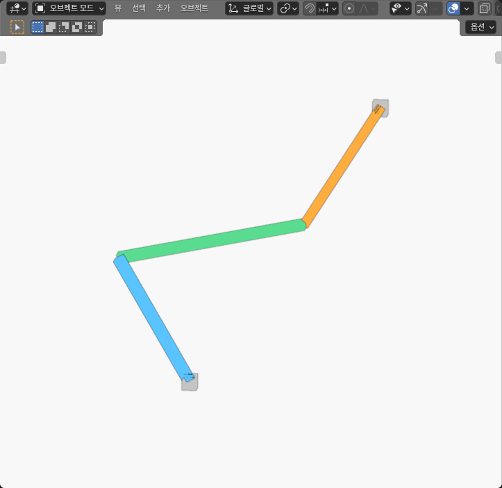
The actual SOLID-editor view shows the 120° cell. The blue input bar starts at the lower gray reference; the green coupler reaches the orange output bar and upper gray reference. Some end interfaces are occluded by the opaque envelopes. The central reference segment is a calculation datum, so there is no extra guide mesh in this image. The sub-millimetre departures use the complete evaluated vertices and finite projection calculation.
A finite segment prevents an easy shortcut
An infinite-line calculation can hide a second failure. If a point projects beyond either end of the intended working segment, its perpendicular distance to the extended line is no longer the relevant distance to the finite datum. The nearest witness becomes an endpoint.
That did not happen in these three cells. Their parameters of approximately 0.866, 0.500, and 0.113 all remained between 0 and 1. Recording u still matters because it proves that the reported perpendicular witnesses belong to the actual 80 mm central segment. Without that check, a small line distance could be reported for a point that has already travelled beyond the intended guide length.
The datum itself needs the same discipline as the moving point. I used the actual end-face centers of the central coupler, not its nominal endpoints, screen orientation, or object origin. The midpoint also came from finite cap centers and all eight corners. That kept the comparison attached to the solids that Blender evaluated.
If a design uses a real guide, the reference should come from that guide’s measured finite geometry instead. If it uses a camera line, seal, slot, or inspection window, the datum should represent that feature and its usable bounds. Choosing the central coupler axis was appropriate for this controlled question because I wanted departure from the central pose, but it is not automatically the correct datum for another mechanism.
Three static points do not certify a straight-line mechanism
This experiment checks three static points; it does not find a continuous maximum. There may be larger or smaller departures between 60°, 90°, and 120°. The point could cross the datum more than once, and another branch could trace a different path. Denser sampling would reveal more static states, but sampling alone would still need a declared coverage and error rule before it could support a full-range claim.
The 4 micrometre coordinate and 8 micrometre comparison bands used in the model were numerical consistency rules. They were not manufacturing tolerances, sensor resolution, bearing clearance, or physical accuracy. The outward-rounded intervals reserve an arithmetic reporting allowance around the captured coordinates. They do not include manufacturing variation or uncertainty in a built linkage.
Nothing in the scene constrained the midpoint to the datum. The gray reference boxes marked ground locations; they were not a slider or rail. There was no contact solver, collision study, force, friction, stress, stiffness, backlash, speed, acceleration, transmission-angle acceptance, or safety analysis. The three cells were authored independently rather than generated as frames of an animation.
The model also did not prove a physical assembly. Rectangular link envelopes can close at mathematical endpoints while real pins, hubs, shoulders, fasteners, and adjacent links compete for axial space. Those packaging questions require their own finite geometry. This result addresses only the midpoint path relative to the declared segment.
For the same reason, “within the numerical zero band” is not a pass against a product requirement. A designer must state an allowable path error and the range over which it applies. The 90° row is a useful central reference, while the two outer rows show that exact closure does not preserve that reference automatically.
Turn the check into a design decision
Start with the point that matters. A coupler midpoint is convenient, but a tool tip, joint center, pad corner, cable attachment, or sensor target may be the real output. Recover it from the actual finite geometry rather than assuming the modeling origin is correct.
Next, define one shared reference in the same coordinate frame. Preserve its finite endpoints. Project each measured point onto the segment, retain the unclamped parameter, and switch to endpoint distance whenever the parameter falls outside 0–1. Keep the signed transverse component alongside the unsigned distance so a reversal across the datum remains visible.
Then separate mechanism validity from path acceptance. Check link spans, endpoints, closure, and assembly branch first. A failed closure is not a path-error sample. A valid closure, however, still needs the path measurement, as these three cells showed.
Finally, compare the observed interval with a declared design allowance across the complete required range. If the error is too large, change a meaningful variable: ground-pivot spacing, side-link length, coupler length, tracer-point location, branch, or the guide architecture. Recompute the full required range after every change rather than correcting one pose and assuming the rest follow.
For this layout, I would carry the recovered midpoints and finite datum into a range check before adding a guide or labeling the output straight. Both outer samples already differ from the central reference. Whether those departures are acceptable depends on a stated path allowance; this experiment supplied three measured samples, not an acceptance specification or a continuous-range certificate.