A parallel gripper should be checked at the pad faces across the required jaw positions. Pads that line up at one opening can tilt relative to each other as the linkage closes. Measure each pad’s angle, the angle between the opposing faces, and the opening at corresponding top and bottom edges. Adjusting one mounting angle can align a chosen pose without correcting the linkage’s changing orientation elsewhere. Parallel faces also need not travel horizontally: the ideal parallelogram here preserves orientation while its pad center follows an arc.
The pad mount determines how the face sits on its carrier; the linkage determines how that carrier moves. Keep the linkage dimensions fixed, record face orientation at several input angles, and apply any mounting correction once. Re-aligning the pad at every pose would hide the behavior being investigated.
The example below uses an authored, ideal planar mechanism. It compares an exact parallelogram, a slightly longer rocker, and that same longer rocker with one fixed pad correction. Its dimensions are deliberately specified for this explanation. They are not dimensions measured from a commercial gripper.
Parallelism belongs to the pad faces
Finger count does not determine face motion. For example, the current Tesollo DG-2F manufacturer page describes an articulated two-finger architecture with six degrees of freedom, three per finger. That is an architecture reference, checked on October 6, 2026. It supplies neither the geometry nor the performance of the simple parallel-link mechanism used here.
If you are still choosing between an articulated finger, a translating jaw and a linkage-driven jaw, start with the gripper architecture and selection guide. This page addresses a narrower design question: after choosing a linkage, do its finite opposing pad faces retain their intended orientation at the positions you need?
A jaw can move inward while its face rotates. Two face centers can have the desired separation while their upper and lower edges do not. A mounting adjustment can align one pose without aligning the others. A center-opening dimension alone resolves none of those ambiguities.
Both mirrored pads have the same height, and corresponding top edges lie at the same mechanism-plane height. A gripper with unequal pads, offsets or three-dimensional articulation needs its own correspondence rule; these numbers should not be transferred to it.
A length change, then one fixed mounting correction
Each jaw has a lower ground pivot A and an upper ground pivot D, separated vertically by 30 mm. The input link runs from A to B and is 45 mm long. The coupler runs from B to C and is 30 mm long. The rocker runs from D to C. Left and right ground pivots are placed at mechanism x coordinates of −80 and +80 mm, with the right mechanism reflected from the left.
The prescribed left input angles are 70°, 60°, 50°, 40°, 30° and 20°, measured from the mechanism’s positive x axis. The order describes six closing configurations. It is not a time schedule, and the angle is not measured from the vertical ground link. Conditions are compared at the same input angle, not at equal aperture. Changing rocker length moves the coupler midpoint; changing the pad mount also shifts its face center through the fixed normal offset.
| Authored condition | Rocker length | Fixed clockwise pad offset | Question isolated |
|---|---|---|---|
| Exact parallelogram | 45 mm | 0° | Does the ideal parallel-motion construction preserve face orientation? |
| Longer rocker | 46.5 mm | 0° | What changes when only the rocker length changes? |
| Longer rocker, adjusted mount | 46.5 mm | Approximately −3.07247° | Does alignment at 20° also align the other five poses? |
The third condition uses one constant offset derived from the ideal dimensions before the experiment. It is added to the left coupler’s clockwise angle from vertical; the right pad follows the exact mirrored construction. This sign convention matters. Entering the value as an ordinary counterclockwise rotation without accounting for the convention could reverse the intended correction.
The links are modeled as closed rectangular prisms, 3 mm wide and 6 mm deep. Each pad is 24 mm high, 16 mm deep and 4 mm thick. Its inner face sits 5 mm inward from the coupler’s joint midpoint. The mounting adjustment rotates the pad frame about that midpoint while retaining this offset distance. Its face center therefore changes position as the frame rotates. This is an authored attachment geometry, not a model of a particular shim or mounting bracket.
The finite links and faces omit bearings, hinge clearances, fasteners and actuator details. Ideal links overlap at joint axes; that is not analyzed as interference. The model answers a coordinate and orientation question before those additional design checks.
Close the loop without changing assembly branches
The official Modern Robotics material on closed-chain kinematics explains that a closed chain must satisfy loop constraints and can have different assemblies and special singular configurations. That provides the conceptual basis for checking closure rather than independently placing each link. The dimensions, circle construction and pad measurements below are our own ideal example; they are not a mechanism taken from that source.
Once A, D and the input angle determine B, joint C must be 30 mm from B and the rocker length from D. These two circles can intersect in two places. Choosing whichever looks convenient at each pose can switch the assembly being compared.
We therefore prescribe one branch for all six poses. Let u be the unit vector from B toward D, and let perp(u) rotate that vector by 90° counterclockwise. If the distance between circle centers is d, the coupler length is c and the rocker length is r, define:
a = (c² − r² + d²) / (2d)
h = sqrt(c² − a²)
C = B + a u − h perp(u)
The minus sign is fixed. A negative square-root argument cannot be repaired by taking its absolute value or silently setting it to zero. It means that this proposed construction has not produced the required real intersection. A tangent intersection also needs separate interpretation, rather than being treated as an ordinary well-separated branch.
For the exact parallelogram on the intended branch, the coupler follows the direction of the ground link. Its midpoint still rises and falls with the input link’s 45 sin(theta) millimeter vertical component. Preserving pad orientation does not produce straight horizontal travel or constant contact height. No slider, guide or part is modeled to correct or assess that path. With the longer rocker, the important comparison is how the coupler’s orientation changes between prescribed poses, not whether a sketch can be assembled at one angle.
Whether a linkage can complete an entire input revolution is a separate problem. The four-bar full-crank and assembly-branch guide addresses that question. Six feasible closing configurations here would not establish full rotation or uninterrupted passage between them.
Compare both edges at the same jaw pose
Report in the mechanism’s own x–y plane. Recover those coordinates by reversing the common three-dimensional rotation and translation before measuring x gaps. A difference along arbitrary global-world x would mix jaw opening with the placement of the whole model.
For each pad, derive the tangent and inward normal from its actual finite face. Record the signed clockwise angle of that tangent from vertical. Then compare the left inward normal with the negative of the right inward normal to obtain the opposing-face angular error. Parallel opposing faces have oppositely directed inward normals, so comparing the two normals directly without reversing one would give the wrong reference.
Keep per-pad angle and pair error separate. In this symmetric planar construction, each pad’s departure produces roughly twice that departure between the opposing faces. Reporting a one-pad angle as pair error understates the wedge.
The face also offers a direct length comparison. Average the two depth-separated corners of each top edge, and do the same for each bottom edge. Subtract left x from right x at corresponding heights. Report the top gap, bottom gap and signed difference top gap − bottom gap, along with the mid-height center aperture.
The sign tells you which end opens farther in the chosen coordinate convention. Its magnitude describes the projected wedge across this finite pad height. It is not a normal clearance between arbitrary nonparallel planes, a contact penetration, or the deflection of a pad under load. No object is placed between these pads to establish contact.
What the 18 static captures measured
On October 6, 2026, one native Blender 5.2.2 LTS operation created and captured all 18 static configurations: three conditions at six input angles. The 144 unshared closed prisms supplied 1,152 evaluated vertices. Independent checking used every corner, complete transforms, topology and outward normals.
Link end-cap centers supplied the joint locations. Actual inner-face corners supplied the pad angles, corresponding edge gaps and center aperture. These are native geometry measurements, separate from the nominal calculation using authored dimensions. No physical gripper, controller, dynamics or continuous motion was executed.
The endpoint rows below summarize the measured geometry. Input angle is the prescribed left-link angle. Pad angle is the left pad’s signed clockwise angle from vertical; pair error is the angle between the opposing faces. Gap and aperture columns are in millimeters.
| Condition | Input | Pad angle | Pair error | Top gap | Bottom gap | Center aperture |
|---|---|---|---|---|---|---|
| Exact parallelogram | 70° | ≈0° | ≈0° | 119.218 | 119.218 | 119.218 |
| Exact parallelogram | 20° | ≈0° | ≈0° | 65.428 | 65.428 | 65.428 |
| Longer rocker | 70° | +9.134° | 18.269° | 110.773 | 118.392 | 114.582 |
| Longer rocker | 20° | +3.072° | 6.145° | 62.548 | 65.120 | 63.834 |
| Adjusted mount | 70° | +6.062° | 12.124° | 111.977 | 117.046 | 114.512 |
| Adjusted mount | 20° | ≈0° | ≈0° | 63.820 | 63.820 | 63.820 |
These are comparisons at the same input angle, not equal aperture. The exact parallelogram retained face orientation across all six captures. Its tiny coordinate-rounding residuals are represented by ≈0; this is not a measurement of physical zero error.
The longer rocker produced a signed top-minus-bottom gap of −7.620 mm at 70° and −2.573 mm at 20°. One fixed mounting correction aligned the 20° configuration numerically, but left −5.069 mm at 70°, with a 114.512 mm center aperture. The remaining 12.124° pair error is distinct from the approximately 6.062° rotation of each pad. The correction removed one angular offset without eliminating its variation across the prescribed positions.
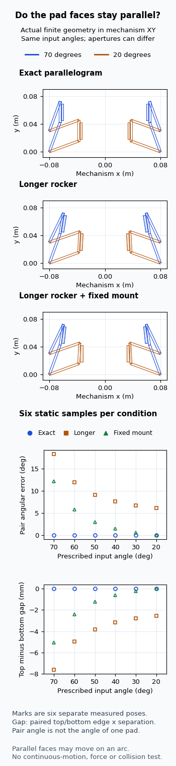
Geometry comparisons allowed 4 micrometers for world vertices, 8 micrometers for derived distances and 0.00002 radians for angles. These are numerical comparison bounds, not manufacturing tolerances or gripper accuracy. No force, friction, compliance, collision or safety result follows from the figure.
Decide whether to change the linkage or the mount
Separate a constant orientation offset from variation with jaw position. A fixed mount adjustment may address a constant offset. If the angle varies across the required positions, aligning one endpoint leaves that variation to be explained by the linkage or attachment geometry.
Also inspect aperture independently. Moving or rotating a finite pad changes where its inner face lies, even when the carrier joint positions remain unchanged. A mount correction that improves alignment at one pose may alter the center aperture and edge openings there. Record those effects rather than treating the angle adjustment as a free correction.
After confirming the sampled face motion, use the finger neck and shoulder clearance guide for the separate problem of whether a finger can reach its intended region around a part. If the faces already have the intended orientation but an object reaches one side first, the gripper opening and object-centering comparison addresses aperture and alignment of the object. Neither check replaces the linkage-generated face-orientation check here.
For a practical record, keep the input-angle convention, selected assembly branch, four link dimensions, fixed mounting offset and face-coordinate definitions together. At every required pose, log both pad angles, the pair angle, the two edge gaps and center aperture. Those fields tell you what needs changing without implying that an ideal geometric comparison has measured grip force, compliance, friction, collision-free motion or hardware performance.