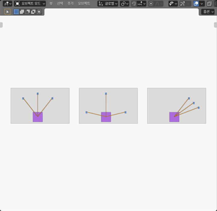
My three-layout Blender experiment showed why tension selection must start with an existence check. The balanced upper fan and the shallow side fan each admitted an explicit positive tension vector inside the declared 1 to 8 N bounds for the same hypothetical 10 N downward load. The one-sided fan did not: every allowable combination produced positive X force, while equilibrium required zero X force.
The contrast came from geometry, not an optimizer. With the middle cable fixed at 7 N, the balanced layout used side tensions of about 1.87500004 N. The shallow layout used about 6.18466061 N on each side. For the one-sided layout, the complete allowable X projection ran from about 2.32847667 to 18.62781336 N, so zero lay outside the interval.
I created and read the three static configurations in an AI-operated Blender 5.2.2 LTS session. Blender supplied finite world-space geometry and cable-reference directions. The load, bounds, and tension certificates were hypothetical mathematical inputs, not measured forces or equipment ratings.
Ask whether any bounded solution exists
For this experiment, a pull direction points from the moving carriage reference C toward a fixed support point P. The three planar unit directions form the columns of U. The declared external force is f = (0, -10) N, and every component of the tension vector t must stay from 1 through 8 N. The condition is:
U t + f = 0
This convention is worth stating because the selected source paper writes its raw cable vector in the opposite geometric direction, from a fixed output A toward a moving anchor B. I used the paper only for the broader idea of deriving cable directions from geometry and intersecting equilibrium solutions with positive lower and upper tension bounds. I kept my moving-to-fixed direction convention explicit when using the paper’s formulation.
The question comes before tension allocation. If the bounded feasible set is empty, changing an objective function cannot produce a valid answer for that load and pose. If the set is nonempty, a later design step can compare continuity, stiffness, energy, or distance from limits.
Three layouts, one load, and one tension box
All three cells used the same carriage reference at the design-frame origin and the same hypothetical load and bounds. Only the fixed anchor layout changed.
The balanced upper fan placed anchors at (-60, 80), (0, 100), and (60, 80) mm. Its measured side directions were approximately (-0.60000002, 0.79999998) and (0.60000002, 0.79999998), with a vertical middle direction.
The shallow side fan moved the side anchors to (-80, 20) and (80, 20) mm while retaining the middle anchor at (0, 100) mm. Its side directions were approximately (-0.97014252, 0.24253554) and (0.97014252, 0.24253554). More of each side cable’s pull was lateral, so the chosen 7 N middle-cable certificate required larger side values.
The one-sided fan placed all three anchors to the positive-X side at (60, 80), (80, 60), and (100, 40) mm. Its X direction components were approximately 0.60000002, 0.79999995, and 0.92847670. Strictly positive tension therefore produced strictly positive total X force.
The table uses outward-rounded intervals from the actual geometry analysis. The middle tension in the two feasible rows is the chosen 7 N certificate parameter. It is not an optimizer output or a universal minimum.
| Layout | Measured direction pattern | Bounded certificate (N) | Complete X projection (N) | Result |
|---|---|---|---|---|
| Balanced upper fan | Symmetric sides, vertical middle | sides 1.875000–1.875001; middle 7.000000 | -4.200001 to 4.200001 | Feasible certificate |
| Shallow side fan | Shallow symmetric sides, vertical middle | sides 6.184660–6.184661; middle 7.000000 | -6.790998 to 6.790998 | Feasible certificate |
| One-sided fan | All three X components positive | No accepted bounded tension vector | 2.328476 to 18.627814 | Zero excluded; infeasible |
These intervals report numerical reconstruction, not force-sensor uncertainty or hardware precision.
Recover directions from whole finite parts
Each cell used two core assemblies. The fixed assembly was a closed support panel with three closed anchor posts. The moving assembly was a closed carriage box. Three full closed square prisms showed the ideal straight reference paths.
The panel measured 240 by 150 by 4 mm. The carriage measured 40 by 40 by 6 mm. Each post measured 6 by 6 by 8 mm and ended at the common Z = 0 reference plane. The 1.5 mm square path prisms sat 2 mm above that plane so their geometry remained visible.
That elevation was a display offset. It was applied equally at both ends of every prism, so it preserved the planar direction. The prisms were not physical cables, their width was not a cable diameter, and the three lower cap centers all referred to one ideal carriage point C. They did not represent three physical attachment fittings.
I recovered each direction from the evaluated means of the complete lower and upper prism caps after removing the cell display translation. The full panels, posts, carriage boxes, and reference prisms remained closed finite meshes. Across the three cells, the model contained 24 such meshes and 192 evaluated world-space vertices. Those counts describe the authored static evidence; they do not add physical fidelity to the cable model.
The fixed support geometry made the layout change readable, while the cap-center method kept the calculation independent of a visible line or object label. The actual screenshot shows the three fans, but it cannot prove force balance. The certificates come from evaluated coordinates and the declared equilibrium equation.
Two layouts have explicit primal certificates
For the balanced fan, fixing the middle cable at 7 N left 3 N of upward force to be supplied by the two side cables. The reconstructed side value was approximately 1.8750000419 N. The outward interval for each side was 1.875000 to 1.875001 N. All three values stayed inside the 1 to 8 N bounds, and both equilibrium residual components stayed within -0.000000000001 to 0.000000000001 N.
For the shallow fan, the same 7 N middle value left the same 3 N upward requirement, but each side direction had only about 0.2425 vertical component. The reconstructed side value was approximately 6.1846606069 N, with an outward interval of 6.184660 to 6.184661 N. Its two residual components fell inside the same tiny numerical interval.
The difference between 1.875 and 6.185 N is useful only under the declared comparison: the same load, bounds, middle value, and symmetric certificate. It does not prove that every shallow-layout solution uses more side tension. It does not rank allocation algorithms or show that 7 N is the best middle value.
A single accepted vector establishes that the bounded set is nonempty. It does not establish uniqueness, stiffness, motion quality, nearby-pose feasibility, or an acceptable operating margin for a real machine.
The one-sided layout has a separating certificate
For infeasibility, failing to find a numerical solution is not enough. I used the X-axis projection y = (1, 0) to bound every allowable cable combination.
Because all three X direction components were positive, each cable’s minimum X contribution occurred at the 1 N lower tension bound and its maximum at the 8 N upper bound. Adding those bounded contributions produced an actual enclosing interval of about 2.3284766706 to 18.6278133650 N. The outward six-decimal report was 2.328476 to 18.627814 N.
The external force had zero X component, so equilibrium required the cable sum to have zero X projection. Zero fell strictly below the entire allowable interval. That separation proves there was no tension vector inside the declared box that balanced this load with these measured directions.
An unconstrained algebraic solve can produce negative or over-limit values, but those are not valid pull-only cable tensions and are not reported as an alternative certificate. The proof uses the whole allowed tension box.
The positive 1 N lower bound is part of this result. Changing the lower bound to zero would change the support interval, but it would not automatically restore feasibility. The vertical 10 N requirement and all upper bounds would still need to be satisfied together in a fresh analysis.
Keep this decision separate from rank and sharing
The current Springer version of record, published September 10, 2025, supports the narrow formulation used here: cable directions arise from attachment geometry, tensions balance an external wrench, and positive lower and upper limits restrict the feasible set. It does not supply my Blender dimensions, chosen load, or results, and I did not execute or benchmark its tension-distribution algorithms: the Berretta et al. article.
The experiment also answers a different question from why two gripper point contacts cannot resist every torque. That article studies spatial wrench rank and friction admissibility. Here the requested force is fixed, the problem is planar, and the decisive constraint is a positive bounded cable box.
It also differs from why four supports do not guarantee equal load sharing. That example begins with a family of equilibrium solutions and asks why the individual reactions are not uniquely selected. The one-sided cable case has no admissible solution at all, while the other two cases need only one explicit certificate to establish existence.
The practical workflow is therefore ordered. Measure the actual pull directions, freeze the load and bounds, prove existence or nonexistence, and only then choose how to allocate tensions inside a nonempty set. This static study did not measure force or tension and did not simulate sag, elasticity, friction, stiffness, pulleys, winches, dynamics, a controller, a workspace, hardware, failure, or safety. It establishes a finite geometric input and a bounded algebraic decision for three authored poses—nothing broader.