Two pickup heads can sit over the same pane with parallel faces and still disagree about where that pane should be. In Physical AI Lab’s AI-assisted Blender experiment, moving the right head sideways left every pad footprint inside the pane, but produced a measured 5.00 mm disagreement between the two inferred pane origins. Tilting that head by 2 degrees also changed its inferred origin. Checking surface normals alone would have missed the translation error.
The useful assembly check is to recover a frame from each head’s actual pickup faces, apply its explicitly defined head-to-pane transform, and compare the resulting pane poses. The finite pane then provides a separate reference for footprint and stand-off measurements. This is a worked virtual geometry experiment performed in Blender 5.2.2 LTS, not an account of operating a glass-handling machine.
Grenzebach’s official glass stacking technology page describes two stacking devices working independently or together on extra-long panes. That current page, checked October 9, 2026, supplied the industrial motivation. Our dimensions, heads and pose offsets are authored schematic inputs; they are not Grenzebach CAD, controller settings or product specifications.
Build two connected heads around one finite pane reference
I built two functional assemblies per test cell: a blue left pickup head and an orange right pickup head. Each contains a crossbeam, two arms and two pads. A gray pane is the common finite reference, rather than a third machine assembly. The five boxes in each head overlap at their intended connections; their grouping is supported by actual shared interior points, not just matching object names.
The pane is 200 × 80 × 2 mm, with its top surface at local Z = 0. Nominal head placements are X = −60 mm and +60 mm. The following bounds define one head before placement; the same recipe is used for both heads. All entries are millimetres in the head’s local coordinates.
| Member | X bounds | Y bounds | Z bounds |
|---|---|---|---|
| Crossbeam | −4 to 4 | −25 to 25 | 20 to 26 |
| Negative-Y arm | −3 to 3 | −23 to −17 | 5 to 22 |
| Positive-Y arm | −3 to 3 | 17 to 23 | 5 to 22 |
| Negative-Y pad | −5 to 5 | −25 to −15 | 2 to 6 |
| Positive-Y pad | −5 to 5 | 15 to 25 | 2 to 6 |
Each member is a closed, outward-oriented eight-corner box. Native evaluated geometry confirmed 44 meshes, 352 world-coordinate vertices and 528 native triangles across four cells. I checked the complete faces and triangles, including the hidden undersides. All eight heads retained their four required member connections.
The 2 mm pad-to-pane gap is deliberate. It keeps the reference geometry separate and lets signed normal distances be measured. It does not represent a suction seal, physical attachment or verified contact condition. Dimensions are converted to metres when constructing and reading Blender coordinates.
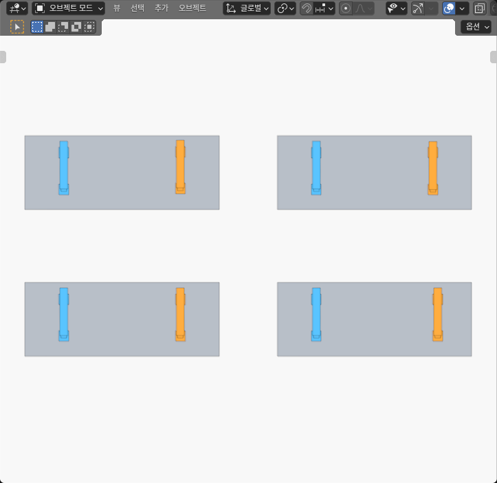
The cells are separated by 260 mm in X and 160 mm in Y for display. These offsets are removed only after reading the actual world-coordinate geometry. They are not differences in pane size or pickup spacing. Opaque members obscure some interfaces in the screenshot; no part was hidden, cut open or made transparent to expose them.
Recover the head frames from complete pickup faces
The head datum is the mean of the two pad bottom-face centres. In the unrotated recipe it is at local (0, 0, 2) mm, so it is not the mesh origin. I recovered positive Y from the direction between the negative-Y and positive-Y pad centres, and positive Z from the opposite of the outward bottom-face normal. Positive X follows from Y × Z. Finite face edges provide an additional check on the orientation and handedness.
For this authored arrangement, the left head’s fixed offset to the pane-top centre is (+60, 0, −2) mm in its measured frame. The right offset is (−60, 0, −2) mm. Applying those offsets gives each head’s independently implied pane origin:
inferred_pane_origin = measured_head_datum + measured_head_axes × fixed_offset
origin_disagreement = inferred_right_origin − inferred_left_origin
Here, “measured head axes” means a matrix whose columns are the recovered unit X, Y and Z axes. The pane orientation is also inferred from the head axes; the fixed orientation offset in this recipe is identity. Both origin and orientation must therefore agree. Using an object’s location property or a pose label would skip the face-derived measurement.
This is a concrete example of the shared-object transforms introduced in our bimanual robot coordination guide. That guide explains the broader control problem. Here the narrower job is reconstructing two finite assembly frames and comparing their implications before discussing control or load sharing. If your frame comes from markers rather than planar pads, the separate near-collinear marker-frame experiment explains why frame quality also needs checking.
Compare four static assembly conditions
I kept the left head and pane reference unchanged within each cell, then changed the right head. Three complete native readbacks covered every cell, and a separate representative capture covered the roll case. An additional readback temporarily applied a proper cyclic coordinate rotation to our own geometry, then restored it exactly. Independently undoing that rotation reproduced the geometry and frame measurements; it was a coordinate check, not another physical condition.
| Right-head condition | Inferred-origin disagreement magnitude | Head-normal disagreement | Right pad stand-off range |
|---|---|---|---|
| Nominal placement | 0.00 mm, within numerical bounds | 0.00° | 2.00 to 2.00 mm |
| +5 mm in X | 5.00 mm | 0.00° | 2.00 to 2.00 mm |
| +3 mm in Z | 3.00 mm | 0.00° | 5.00 to 5.00 mm |
| +2° roll about the pad-centre datum | 0.07 mm | 2.00° | 1.13 to 2.87 mm |
These are rounded results from the actual coordinates. The independent calculation found approximately 0.0698 mm of origin disagreement in the roll case. All four pad bottom faces in every cell projected completely inside the finite pane, and every measured pad corner had positive stand-off. Passing those checks did not make the shifted or tilted heads imply a common pane pose.
The sideways shift is the clearest counterexample: the normals and pad gaps remain nominal, but the inferred pane origins differ along X. The height shift preserves normal alignment too, while changing both the inferred origin and the right-side gap. Neither failure is diagnosed by asking only whether the heads are parallel.
I used a 4 micrometre coordinate correspondence allowance and an 8 micrometre comparison allowance for the numerical checks, with a separate 8 microradian angle band. Those are calculation bounds for this model, not installation tolerances. The nominal residual is small within those bounds; “0.00 mm” is a rounded report, not a claim of exact physical coincidence.
Why a tilted head also changes the inferred origin
For the roll case, I rotated the right assembly about its measured pad-centre datum, not about the boxes’ local origin. That keeps the datum fixed while the head axes turn. However, the fixed head-to-pane offset still contains a −2 mm Z component. Rotating that offset changes where the head predicts the pane-top centre should be.
The measured disagreement was approximately +0.0698 mm in Y and +0.0012 mm in Z, with X near zero within the numerical bounds. The right head’s in-plane yaw remained zero, while its normal tilted by approximately 2 degrees. Setting the translation result to zero because the rotation pivot stayed fixed would have discarded the calibrated-offset effect.
The finite pads also matter. A single pad-centre gap would not describe the tilted lower faces: their complete corner distances ranged from about 1.13 to 2.87 mm across the two pads. Measuring whole faces distinguishes a reference-plane projection from a uniform gap. It still provides no evidence about sealing, glass stress or suction force.
Use the closure check before adding a handling model
To reproduce the diagnostic, build the five closed boxes from the bounds above, duplicate the head at the two nominal X placements, and add the finite pane. Recover each frame from its complete bottom faces. Apply the specified offsets, then compare the inferred origins and orientations. Introduce one change at a time: 5 mm X translation, 3 mm Z translation, or a 2-degree roll about the shared pad-centre datum.
For another assembly, replace the offsets with that assembly’s defined or independently established transforms. Moving a calibration offset merely to make a residual disappear would change the question being tested. Keep frame construction, transform definition, finite footprint coverage and gap measurements separate so a passing secondary check cannot hide a pose mismatch.
I independently recalculated all world-coordinate corners, closed-face geometry and connected-head interior checks from the saved native arrays. The actual-data reader also rejected 40 deliberately corrupted evidence copies. An initial corruption-test field reference was corrected without recreating the Blender geometry. These checks support this virtual result; they do not turn it into an expert-reviewed industrial trial.
Only four static placements were tested. No coordinated motion, controller calibration, continuous path, suction, force, deformation, capacity, cycle time or hardware safety was tested. Existing Blender scenes and working state were preserved. The next useful modelling step is to define the intended contact and shared-object motion, then evaluate those conditions explicitly. This experiment establishes the prior geometric question: do both assembled heads actually imply the same rigid-pane pose?