Two plate openings can remain parallel at the same axial spacing while their shared opening shrinks substantially. In our AI-assisted Blender study, a 40 × 24 mm fixed opening and a 32 × 20 mm moving opening shared approximately 640, 480, 240 and 0 mm² at four horizontal offsets. The 2 mm gap between the plates stayed constant. That gap therefore did not explain how much of the projected opening remained available.
This is an actual virtual geometry experiment by Physical AI Lab. We constructed two connected ring assemblies, read their complete evaluated coordinates from Blender, and calculated the intersection of their empty regions. We did not run fluid, contact, thermal, robot-control or hardware tests. The useful result is a repeatable way to separate plate spacing from projected opening overlap before a more detailed simulation or physical trial.
Why measure the empty opening rather than the plate outline?
For a plate mechanism, “the parts line up” can describe several different conditions: parallel faces, acceptable spacing, an opening centered on another opening, or a sufficient common passage. A single screenshot or distance measurement cannot distinguish all of them.
Our motivation came from Krosaki’s official REX-ROBO-LSG maintenance page, checked on October 9, 2026. It lists plate and lower-nozzle exchange among its maintenance functions, alongside frame opening and closing and other tasks. That establishes a practical reason to think about plate interfaces. It supplies neither the dimensions nor the geometry used here, and it does not validate this experiment or provide an acceptance threshold for it.
We deliberately reduced the problem to two rectangular openings. Each opening is a genuine vacant region surrounded by four closed solids. We measured the projected intersection of those vacancies, rather than intersecting the solids or reading a decorative hole marker. This matters because a model can show correct outer dimensions and still describe its passage incorrectly.
A related distinction appears in our tool-changer port-clocking experiment: two ports can geometrically coincide while connecting the wrong persistent circuit identities. Here there is only one unlabeled opening pair. The question is how much common area remains during translation, rather than which circuit connects to which.
Build two complete rings with a reproducible coordinate recipe
We used Blender 5.2.2 LTS and treated coordinates as metres. The dimensions below are authored schematic inputs, not vendor CAD or manufacturing tolerances. Each case contains a blue fixed gate and an orange moving plate. Both cores consist of four separate, closed box meshes that overlap at the corners, giving each core a connected solid union.
| Core | Outer rectangle | Empty opening | Local Z interval |
|---|---|---|---|
| Fixed gate | 80 × 60 mm | 40 × 24 mm | −8 to 0 mm |
| Moving plate | 70 × 50 mm | 32 × 20 mm | 2 to 8 mm |
Both openings start centered on their core’s local origin. The fixed gate’s opening extends from −20 to +20 mm in X and −12 to +12 mm in Y. The moving plate’s opening extends from −16 to +16 mm in X and −10 to +10 mm in Y. Its lower face begins 2 mm above the fixed gate’s upper face. That positive gap is a diagnostic reference spacing; the two cores are not seated against one another.
The complete member bounds are straightforward to reproduce. For the fixed gate, the left and right bars occupy X intervals −40 to −20 mm and +20 to +40 mm, both with Y from −30 to +30 mm. The lower and upper bars occupy Y intervals −30 to −12 mm and +12 to +30 mm, both with X from −40 to +40 mm. All four use Z from −8 to 0 mm.
For the moving plate, the left and right bars occupy X intervals −35 to −16 mm and +16 to +35 mm, both with Y from −25 to +25 mm. Its lower and upper bars occupy Y intervals −25 to −10 mm and +10 to +25 mm, both with X from −35 to +35 mm. All four use Z from 2 to 8 mm. The bars intentionally overlap at their corners; none crosses its core’s vacant opening.
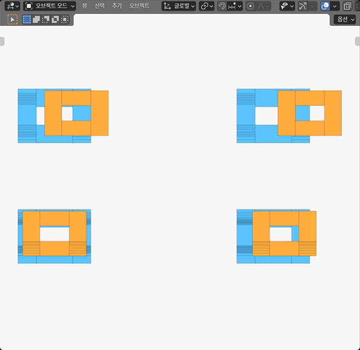
We made four independent static cells and translated the entire moving core by 0, 12, 24 or 40 mm along X. We kept every member’s rotation and shape unchanged. Cell origins of (0, 0), (240, 0), (0, 140) and (240, 140) mm simply separate the examples for display; these layout offsets are removed when reporting opening centroids.
Across the four cells, Blender contained 32 unshared box meshes, 256 evaluated WORLD vertices and 384 native triangles. We read complete geometry three times with different case foci and retained a separate full representative read. These counts describe the model and readback coverage; they are not a performance benchmark.
Recover the vacant boundaries from actual finite inner faces
We did not use the authored opening dimensions as the final measurements. For each actual ring, we read the four inner wall faces that point into its opening. Their complete WORLD vertices define the left, right, lower and upper boundaries. The endpoints of the resulting loop must lie on the finite wall faces, rather than merely on infinite extensions of their planes.
The distinction is useful in less tidy models. A wall plane might appear to bound an opening even though the wall ends before the required corner. A warped box can also have plausible minimum and maximum coordinates without representing the intended solid. Our canonical checks require complete closed topology, outward native triangles and the actual Cartesian corner structure. They also check that every member remains outside the open region and that the four bars have genuine overlapping interiors at the intended connections.
Once the two measured loops are expressed in the same plane, their intersection gives the common projected opening. In this axis-aligned experiment, the calculation reduces to the following conceptual Python function:
def shared_rectangle(a, b):
    # a and b are measured (xmin, xmax, ymin, ymax) in metres.
    xmin, xmax = max(a[0], b[0]), min(a[1], b[1])
    ymin, ymax = max(a[2], b[2]), min(a[3], b[3])
    width = max(0.0, xmax - xmin)
    height = max(0.0, ymax - ymin)
    area = width * height
    center = ((xmin + xmax) / 2, (ymin + ymax) / 2) if area > 0 else None
    return area, width, center
The function illustrates the geometry after the finite openings have been established. It is not a Blender geometry validator, and an arbitrary rotated or nonrectangular opening needs a polygon-intersection method instead. We used actual native-face boundaries and independent calculations for the experiment, with exact rational arithmetic and outward numerical bounds in the detailed check.
What changed at the four measured offsets?
The following values are rounded from the actual evaluated geometry to 0.01 mm or 0.01 mm². The centroid is measured relative to the fixed opening’s center after removing the display-cell translation. Y remained approximately zero in the positive-area cases.
| Moving-core X offset | Common projected area | Remaining X width | Common-area centroid X |
|---|---|---|---|
| 0 mm | 640.00 mm² | 32.00 mm | 0.00 mm |
| 12 mm | 480.00 mm² | 24.00 mm | 8.00 mm |
| 24 mm | 240.00 mm² | 12.00 mm | 14.00 mm |
| 40 mm | 0.00 mm² | 0.00 mm | Undefined |
At zero offset, the smaller moving opening lay fully within the fixed opening, so all of its projected area remained common. At 12 mm, the overlap covered approximately 75% of the moving opening; at 24 mm, it covered approximately 37.5%. Those are geometric area fractions, not measured flow-rate fractions.
The centroid moved to the right as the common region narrowed. A “still open” binary check would miss that change in the position of the available passage. At 40 mm, the two projected openings were separated by approximately 4 mm along X. There was no positive common area and therefore no common-area centroid to report. Assigning that centroid a zero value would misleadingly describe it as centered.
The complete-core axial spacing remained approximately 2.00 mm in every case. This was the clearest contrast in the experiment: unchanged spacing and unchanged parallel orientation coexisted with very different projected opening areas. Positive axial spacing is neither an overlap measurement nor evidence of physical contact or sealing.
Use the result as a geometry check before a larger test
The practical next step is to define what a real mechanism needs from its interface. If the requirement concerns a common passage, measure its complete finite boundary and area. If passage location matters, track the centroid as well. If the requirement concerns circuit identity, seating, leakage or a robot’s approach path, add the corresponding separate checks; this experiment does not answer those questions.
For reproduction, keep each core’s membership explicit and move all four of its members together. Check the inner wall orientation, verify finite boundary coverage, and report an absent centroid when the intersection has no positive area. Keep display offsets separate from physical changes so that the layout does not contaminate the reported translation or centroid.
An opaque viewport is useful for inspecting the assembled model but can hide inner faces or portions of an opening. Our image preserves complete geometry and is not an area measurement. The measured results come from evaluated coordinates and native topology. The schematic rings also overlap internally at their corners; they are a connected geometry model, not a detailed manufactured plate or joining specification.
Our numerical correspondence and comparison bounds are computational checks, not hardware tolerances. The study does not establish molten-material flow, pressure loss, thermal deformation, refractory wear, contact, support, seal quality, controller behavior, maintenance performance or safety. Those would require suitable physical properties, boundary conditions, equipment and validation. What we established here is narrower and reusable: the common vacant opening can shrink to zero while the plate gap stays the same.