Bimanual coordination is not two independent arm trajectories started at the same time. When both hands hold one rigid object, their end effectors form a closed kinematic chain. Relative pose error becomes contact force, object deformation or slip.
The controller must move the object while maintaining a feasible relationship between the arms, distributing load and respecting joint, torque, collision and grasp constraints. Timing error and calibration bias can create internal force even when each arm tracks its own command accurately.
Use this guide with the whole-body control guide and coordinate-frame guide. Validate object motion and closed-chain stress together.
Model one object constraint instead of two unrelated goals
Define the object frame and each grasp transform. The left and right tool poses should be generated from a shared object pose or a consistent relative constraint. Independent targets can disagree by millimeters or fractions of a degree that become large forces on a stiff object.
Keep grasp compliance and allowed relative motion explicit. A flexible bag, long board and rigid fixture need different constraint models and force limits.

Separate absolute and relative coordinates
Absolute coordinates describe where the object or cooperative system moves in the workcell. Relative coordinates describe the pose between the end effectors or grasp frames. This decomposition separates task motion from the closed-chain relationship.
Define orientation interpolation and transform direction. An apparently small sign or frame error can command the arms to twist the object in opposite directions.
| Coordinate or variable | Controls | Primary constraint | Failure symptom |
|---|---|---|---|
| Object absolute pose | Task motion | World collision and reach | Wrong placement |
| Tool relative pose | Closed chain | Grasp geometry | Arms fight |
| Net object wrench | Acceleration or contact | Payload and task force | Tracking loss |
| Internal wrench | Grip and preload | Damage and actuator limit | Heating or bending |
| Null-space posture | Joint margin | Self-collision | Singularity |
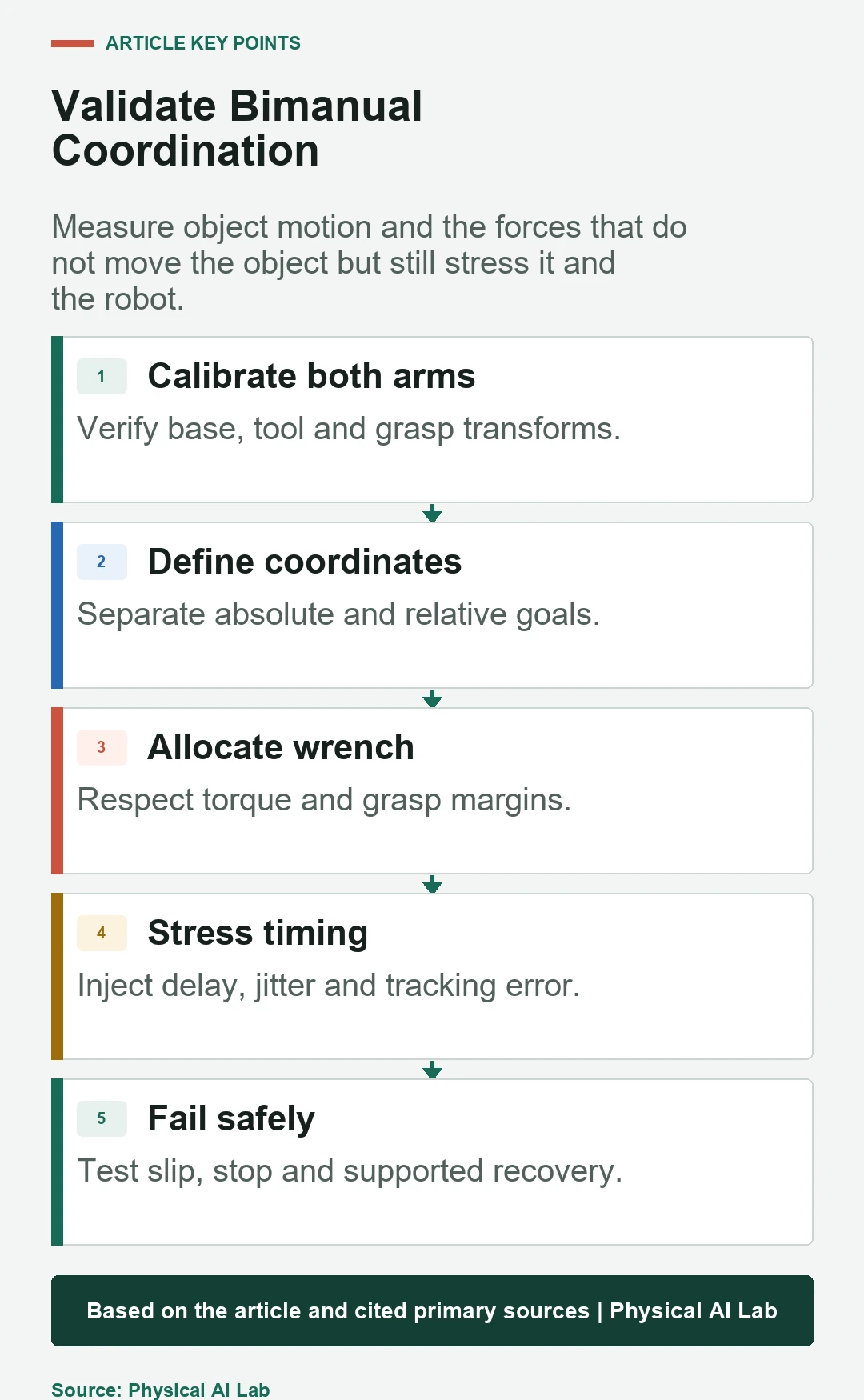
Calibrate both arms into a common physical frame
Base, joint zero, tool center point and grasp transforms from both arms accumulate in the relative error. Calibrating each arm against separate targets can leave a cross-arm bias that appears only after both contact the same object.
Use a common artifact and measure relative pose and force after zeroing sensors. Follow the robot calibration workflow and retain calibration versions with every test.
Solve closed-chain motion with all constraints present
A closed-chain planner or controller must satisfy both grasp relationships while respecting joints and collisions. Sampling one arm first and solving the other can be useful, but it may bias the solution or fail in narrow shared workspaces.
The current MoveIt dual-arm documentation shows multi-arm configuration and planning groups. It does not by itself create object-force coordination or safety behavior.
Choose master-slave or symmetric roles from the task
A master-slave design lets one arm lead motion while the other follows relative pose or force. A symmetric design distributes task variables across both arms. Neither is universally superior; tooling, stiffness, sensing and reach determine the useful allocation.
Make role switches explicit and bumpless. A sudden change in reference or force integrator can shock the object even when each controller is stable alone.
Measure internal force separately from net object wrench
Internal force does not accelerate the rigid object, but it loads the grasps, object and joints. A system can show excellent object-pose tracking while squeezing, stretching or twisting itself. Wrist sensors or joint-torque estimates can expose this hidden stress.
Some preload may improve grasp stability. Bound it from object strength, contact friction, sensor bias and actuator thermal limits rather than forcing it to zero by rule.
Allocate load by torque and grasp margin
Equal load sharing is simple but may be poor near one arm’s singularity, joint limit or weak grasp. Allocation can account for torque headroom, manipulability, contact margin and the direction of the task wrench.
Track the allocation during motion. A feasible static split may become infeasible as the object rotates or the mobile base moves.
Control timing, jitter and communication loss
The arms need a shared time basis for commands, joint state and force. Delay difference appears as relative tracking error, particularly during fast or stiff motion. Average latency alone hides damaging jitter and packet loss.
Use the time-synchronization guide and inject bounded delay in tests. Slow or stop both arms when synchronization quality leaves the qualified envelope.
Plan self-collision, object collision and visibility
Two arms create more self-collision pairs and can block each other’s cameras. The held object becomes part of the moving collision geometry. Cables and temporary support fixtures may be absent from the nominal model.
Check the entire approach, cooperative motion, regrasp and retreat. Update object geometry and attached-body state at the same event used by both arms.
Treat regrasp as a supported transition
During regrasp, one hand may support the full load while the other unloads, moves and contacts again. The support grasp, object motion and next contact must remain inside their margins throughout the transition.
Define verification before load transfer: contact established, force direction plausible, pose within tolerance and receiving arm able to accept the load. Abort to a supported state when any gate fails.
Coordinate protective stops and one-arm failures
If one arm stops, the other should not continue pulling a shared object under the old command. The safe response depends on load, gravity, brakes, fixture and human access. Both arms may need a synchronized stop, controlled lowering or maintained support.
Test sensor dropout, drive fault, protective stop, slipping grasp and object breakaway. A recovery procedure must not re-enable one arm against a latched or unpowered partner.
| Test factor | Variation | Metric | Required failure evidence |
|---|---|---|---|
| Object | Mass, stiffness, size | Pose and internal force | Deformation |
| Calibration | Relative bias injection | Force versus bias | Transform version |
| Timing | Delay and jitter | Relative error and peak force | Clock trace |
| Load share | Asymmetric reach and torque | Margin and temperature | Joint state |
| Fault | Stop, slip, sensor loss | Safe-state success | Response timeline |
Release a bimanual acceptance checklist
Document object and grasp frames, absolute and relative goals, load allocation, internal-force limits, synchronization threshold, collision model, stop behavior and supported recovery. Store both arms’ commands and measurements on one time axis.
Close validation with the following checklist.
- Calibrate the two-arm relative geometry.
- Control object and relative coordinates explicitly.
- Measure net and internal wrench separately.
- Test delay, jitter, collision and load transfer.
- Coordinate one-arm faults into a system safe state.
Frequently asked questions
Can two arm paths be planned independently and executed together?
Only for tasks without a shared rigid constraint and after collision checks; shared-object work needs a consistent relative relationship.
Is master-slave control worse than symmetric control?
No. It is a role allocation with different tradeoffs; task geometry, stiffness, sensing and reach determine suitability.
Should internal force always be zero?
No. Controlled preload may stabilize a grasp, but it must remain inside object, contact, sensor and actuator limits.
What happens if one arm enters a protective stop?
The other arm needs a coordinated predefined response, such as synchronized stop, support or controlled lowering, validated for the load.
What are the main bimanual metrics?
Object pose, relative pose, net and internal wrench, load-share margin, collision clearance, timing and fault-recovery success.
Closed-Chain Internal-Force and Stop Boundary
A bimanual system is one closed-chain machine during shared contact. Safety and recovery logic must coordinate both arms and the supported object, not merely two controllers.