Coil destrapping needs two placement checks: the full strap width must fall between the head’s inner cheeks, and every other part of the head must clear the coil and its end-lap. A blade overlapping the strap establishes neither condition by itself.
In our Blender geometry experiment, an 8mm-wide strap fitted inside a 10mm opening with approximately 1mm left on each side. Shifting the whole head 3mm along the coil axis left approximately 2mm of strap outside the opening. Separately, turning the modeled end-lap toward the head caused interference with the blade reference and both cheeks, even when the strap was centered. Only the centered, lap-clear configuration passed our static geometric criteria. No strap was cut and no physical cutter was tested.
Why the end-lap belongs in the placement question
Signode’s RCU description describes locating straps and the coil end-lap during rotation, orienting the end-lap, retaining the strap during cutting, and collecting the removed material. That sequence makes orientation relevant before selecting a cutting position. It supplies no dimensioned drawing for the geometry used here.
Polytec’s PolyDESTRAPPING description describes 3D strap detection and lists coil-end identification as optional. It also describes selecting a cutting point to protect the outside surface. These are manufacturer descriptions; the page supplies no detection-error bound or tested recovery procedure for an ambiguous edge.
We directly checked both pages on October 12, 2026, Korea time. Their exact publication and update dates were not identified. The experiment below uses independently authored generic geometry, without treating either description as evidence of our model’s performance.
What we assembled in Blender
The first functional core contains three closed solids: an annular coil body, a circumferential strap, and a finite step representing the end-lap. The coil has a nominal outside diameter of 80mm, a 36mm bore and a 60mm axial width. Both the body and strap use 32-sided annular sections; the real hole remains in their modeled topology. They are polygonal solids rather than analytical cylinders or bounding boxes.
The strap occupies an 8mm axial interval, centered on the coil. Its nominal inner and outer radii are 39.5mm and 41mm. The 0.5mm radial overlap with the coil gives the rigid virtual core a connected geometric union. It is an explicit modeling choice, not evidence of adhesion, strap tension or a realistic material interface.
The lap is a closed, extruded quadrilateral, 20mm wide along the coil axis. Its section joins endpoints at nominal radii of 39.5mm and 42mm, at angles of minus and plus 15 degrees around the top. Those endpoints make finite straight boundaries. In the throat-facing configuration, its actual maximum height is approximately 40.569mm above the coil axis; the 42mm endpoint radius is not its vertical height. This distinction matters when comparing the local step with a tool above the coil.
The second core is a complete five-member open head: a blade reference, two opposing cheeks, a rear bridge and a carriage arm. The cheeks’ inner faces define a nominal 10mm axial opening. The blade spans 11mm axially, 2mm transversely and 1mm radially. Its radial interval starts at 40.25mm, above the nominal coil surface but within part of the strap’s modeled thickness. The blade and cheeks connect geometrically to the bridge and arm; none was detached or hidden to improve clearance.
These small dimensions make a controlled geometry example. They are not manufacturer CAD, a production coil specification or recommended cutter dimensions.
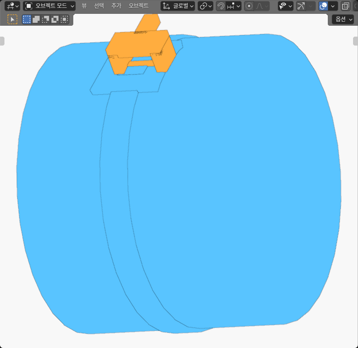
The four placements we actually checked
We crossed two lap phases with two head registrations. To move the lap away from the head, we rotated the entire three-member coil core 180 degrees about the coil axis. To create axial misregistration, we translated the entire five-member head 3mm along that axis. Individual members retained their original shapes and stayed together.
Each configuration occupies a separate display cell in one Blender scene. Common cell translations were removed from the calculations, so screen arrangement does not create a measured clearance. We collected three full geometry readbacks covering all four static configurations. Alternating the readback focus checked repeatability; it was not a physical approach, rotation or cutting trajectory.
| Lap phase | Head shift | Strap inside opening | Unwanted overlaps | Geometry result |
|---|---|---|---|---|
| Away | 0mm | About 8mm of 8mm | 0 pairs | Pass |
| Toward | 0mm | About 8mm of 8mm | 3 pairs | Reject |
| Away | +3mm | About 6mm of 8mm | 1 pair | Reject |
| Toward | +3mm | About 6mm of 8mm | 4 pairs | Reject |
The table reports measured virtual geometry, rounded for readability. A pass requires strict full-width registration, a positive intended strap/blade reference overlap, and strict separation of all 14 other cross-core pairs. Boundary uncertainty would require a hold. None of these four cases produced such an unresolved boundary.
Centering the strap does not clear the local step
With no head shift, the measured strap edges were approximately minus and plus 4mm from the datum. The inner cheek faces were approximately minus and plus 5mm. Both configurations therefore retained approximately 1mm of axial registration margin on each side.
The lap-facing centered case still failed. Its lap overlapped the blade reference by approximately 7.015mm³ and each cheek by approximately 1.653mm³. These positive virtual volumes identify geometric interference. They are not contact force, deformation or damage measurements. The bridge and arm cleared the lap, but checking only those members would miss the three interfering pairs.
In the lap-clear centered case, all 14 nonreference cross-core pairs were strictly separated. The closest coil-body/blade gap was approximately 0.250mm. The intended strap/blade reference overlap was approximately 11.212mm³. That overlap is a geometric target deliberately included in the model; it does not establish a cut depth, successful severing or a safe operating margin.
Moving the head can preserve overlap while losing full-width registration
The 3mm shift moved the opening from approximately [-5, 5]mm to [-2, 8]mm relative to the coil datum. The strap remained approximately [-4, 4]mm. About 6mm lay inside the opening and about 2mm lay outside its negative-axis edge. The two registration margins were approximately minus 2mm and plus 4mm.
The blade still overlapped the strap by approximately 9.110mm³. Looking only for a positive overlap would therefore accept an incompletely registered operation. The negative-axis cheek also intersected the strap, giving one unwanted cross-core pair even with the lap away. With the lap facing the head, three additional lap/head intersections remained, producing four unwanted pairs altogether.
Registration here means the entire axial strap width lies between the opposing finite cheek planes. It does not mean the full circular strap is enclosed inside a small rectangular throat, nor does it prove that the head can enter or leave this position.
How we checked the finite solids
The actual Blender scene contains 32 meshes, 1,216 world-coordinate vertices and 2,336 native triangles across the four configurations. We exported both authored and evaluated geometry, including faces, edges, normals and measured transforms. An independent calculation reconstructed the finite surfaces and annular holes from those actual arrays, then checked all 112 unique member pairs: 60 across the two cores and 52 within them. All 32 prescribed connections had strictly positive geometric union.
We also applied a proper coordinate-axis permutation to the same objects, captured their actual world coordinates again, and restored all 33 object matrices, including the unused reference camera. The independent check compared complete triangle-based distance and volume enclosures without fitting the transformed mesh back to an ideal shape. All comparisons passed. Separate checks rejected 60 corrupted copies of the actual packet; the genuine packet stayed unchanged.
The fixed calculation bounds were 4µm for coordinate correspondence, 8µm for comparison, 8µrad for triangle-normal correspondence and 20nm of arithmetic reserve. These are computational checks, not manufacturing tolerances. We preserved every pre-existing scene, its geometry, context, display and image inventory. The illustration is an unedited original opaque SOLID viewport capture; no rendering, transparency or cutaway was used.
How to use the result in a placement workflow
Treat strap-edge registration and end-lap clearance as separate inputs. First locate both axial strap edges relative to the head’s actual opening. Then check the complete head against the coil surface and finite end-lap geometry, identifying the intended operation reference separately from every other pair. An unresolved boundary should remain unresolved until better evidence is available.
The coil catcher experiment examines how changing diameter affects clearance around an arm positioned relative to a tangent. Here the diameter stays constant while lap phase and axial registration change. The sandwich closure experiment illustrates why partial overlap does not establish complete operation-reference containment; its planar calculation cannot establish coil-tool clearance.
Our four static checks do not demonstrate perception accuracy, a collision-free path, strap severing, retained tension, recoil control or hardware safety. We ran no contact, force or material solver and tested no commercial product. Those questions need their own sensing, material, actuation and operating-sequence evidence. The useful result here is narrower: preserving blade/strap overlap is insufficient unless full-width registration and whole-head clearance also pass.