A sandwich can have a large shared footprint while a small part of a fixed cutting reference falls outside it. In this Blender geometry study, shifting the upper half by 23 mm left about 75.53% of the original footprint shared with the lower half. Yet approximately 0.35 mm of the 70 mm diagonal reference line was outside that shared region. The placement therefore failed the defined full-line condition, despite its substantial overlap.
For a downstream operation whose position is fixed, the useful decision is whether its entire required region remains within the assembled product. Shared area helps describe the placement, but it cannot answer that question alone. Here, checking the finite polygon boundary and the complete line separated three compatible placements from one incompatible placement. The scope is a static, AI-assisted Blender geometry study; sandwich-cutting and gripping were not tested.
Why closure and downstream alignment need separate checks
Grote’s sandwich-assembly robotics page lists ingredient assembly and alignment among its applications. Its AC60 cutter page offers straight or 45-degree half cuts. Together, these manufacturer descriptions motivate a placement question: does the assembled product still cover the region required by the next operation? They do not establish that the authored poses below match a particular production line. Both official pages were checked on October 11, 2026; their publication dates were not established. Grote’s sandwich-assembly robotics description and Grote’s AC60 sandwich-cutter description.
The geometry below is independently authored. Its dimensions, corner chamfers, poses and 70 mm reference do not come from the vendor’s machine. The experiment does not reproduce that production line or assess its performance. It isolates one question: if the downstream numerical line stays fixed relative to the lower half, does the upper half still cover the entire line after closure?
This distinction matters when a placement check uses the product center or reports only an overlap percentage. Those quantities summarize geometry. A fixed operation has its own finite extent, which needs a separate containment check.
The two assemblies and the fixed reference
Each modeled half has an octagonal footprint within a 96 × 64 mm rectangle, with four 8 mm corner chamfers. The nominal footprint area is 6,016 mm². Both halves are 10 mm thick: the lower half occupies Z = 0–10 mm, and the upper half occupies Z = 10–20 mm. Their facing closure surfaces are consequently defined around Z = 10 mm.
There are eight members in each configuration, grouped into two assemblies. The lower assembly consists of the lower half, a fixture and two datum blocks. The upper assembly consists of the upper half, a support and two generic fingers. Every prescribed upper placement moves that complete upper assembly rigidly; the fingers are not independently adjusted to manufacture a better result. The lower assembly remains fixed.
The reference is a straight, 70 mm numerical segment centered on the lower half at 45 degrees in its XY plane. Its nominal endpoints are approximately (−24.75, −24.75) mm and (+24.75, +24.75) mm in the lower frame. It is not a blade mesh, a robot trajectory or an executed cut.
We compared alignment, a 23 mm X translation, a 12-degree rotation, and a combined 8 mm X / −6 mm Y translation with that rotation. These are four separate static placements, not intermediate samples certified along a continuous movement.
Large overlap did not guarantee full-line coverage
The following values come from the captured Blender geometry. Areas and lengths are rounded; “complete” refers to the numerical segment within both projected finite footprints.
| Upper assembly placement | Shared area | Share of aligned footprint | Complete fixed line? | Length outside shared region |
|---|---|---|---|---|
| Aligned | 6,016.00 mm² | 100.00% | Yes | 0.00 mm |
| X +23 mm | 4,544.00 mm² | 75.53% | No | About 0.35 mm |
| Rotation +12° | 5,552.97 mm² | 92.30% | Yes | 0.00 mm |
| X +8 mm, Y −6 mm, rotation +12° | 5,002.28 mm² | 83.15% | Yes | 0.00 mm |
The X-only translation is the instructive case. About 69.65 mm of the reference remains included, but its negative endpoint crosses a chamfer boundary. Its positive endpoint remains inside. The relevant condition requires the full 70 mm, so a small excluded portion still changes the answer.
The rotated placements demonstrate why this is not simply an area threshold. Their shared areas differ, but both include the complete segment. In the combined placement, the closer reference endpoint is about 5.41 mm from the shared polygon boundary. That distance describes this model’s geometry; it is not a recommended production margin.
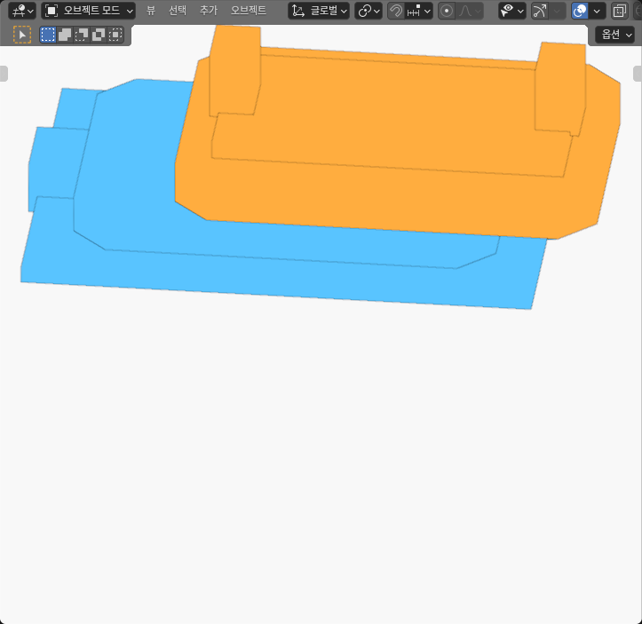
Check the finite boundary rather than its bounding rectangle
The failure occurs near a chamfer, where an axis-aligned bounding rectangle includes space outside the actual footprint. In the translated case, the negative endpoint lies within the shared bounding rectangle. A rectangle-only check would therefore accept an endpoint that the finite polygon excludes. Checking the center would miss the same problem, because the center remains inside.
We formed the common footprint from the complete projected closure polygons, then clipped the entire fixed segment against every boundary of that common polygon. This yields the included parameter interval and the excluded length. It does not depend on choosing a few sample points along the line. Endpoint-to-boundary distances provide an additional finite witness for the result.
For these convex footprints, including both endpoints in the common polygon implies inclusion of the straight segment between them. That implication depends on convexity. With a concave footprint, a hole or a curved operation, endpoint checks alone would be insufficient: the complete operation region would still need to be evaluated.
The related OES sample-placement study addresses a different application of this distinction. A placement can satisfy the support-foot areas while a separate analysis footprint crosses an excluded region. Each required finite region needs its own check.
What the actual geometry check establishes
The calculation used captured mesh vertices and triangles rather than replacing them with the authored dimensions. It first verified the closed finite prism geometry, recovered the lower reference frame from the actual geometry and transformations, and removed the offsets used to display the four configurations separately. Those display offsets do not change the relative placements being compared.
The opposing closure faces were geometrically compatible within the unchanged 8 micrometer comparison band. The footprint and line results are projected geometric relations under that bound. They do not establish exact physical contact, contact pressure or compression. Boundary-only relations remain unresolved as exact contact and are not counted as positive-volume connections.
The modeled members also remained connected within their intended assemblies, and the other lower-to-upper member pairs were separated at these static placements. These checks prevent a favorable footprint result from concealing an unrelated solid intersection in the modeled configuration. They still provide no proof of collision-free entry, removal or movement between configurations.
The reclaimed-beam closure study gives another reason to define the interface condition explicitly: projected overlap can remain unchanged while corresponding faces fail to close together. Here, face compatibility and full-line containment are likewise separate requirements.
A numerical limit is useful only with its assumptions
For the authored, unrotated X-only model, the limiting translation can be written as 72 − 35√2 mm, approximately 22.50 mm. It follows from the fixed diagonal endpoint meeting the upper half’s chamfer boundary. At 23 mm, that endpoint is beyond the modeled limit, consistent with the approximately 0.35 mm excluded segment measured from the captured geometry.
This boundary is not a robot positioning tolerance or a cutter setting. It assumes these particular octagons, the centered 70 mm segment, no rotation, and unchanged shape. Change the segment length, corner geometry or relative angle and the condition changes. Real product deformation and measurement uncertainty require a separately justified allowance; none was fitted into this experiment.
Use the result to define the placement decision
For a known downstream window, establish its coordinate frame and complete required extent first. Then reconstruct the relative placement of the two halves and test that extent against their shared finite footprint. Record both the common area and the actual excluded portion, because they answer different questions.
If the full extent is not contained, realigning the closure is one candidate correction. Moving the downstream operation is another, but it changes the reference and must be checked again. A large overlap percentage or an acceptable center position should not replace that new check.
Before applying this reasoning to food handling, replace the generic solids with an appropriately measured product model and establish the real operation’s requirements. This study tested no food, gripper, pressing force, cut, hygiene procedure, throughput, safety function or hardware. Its practical contribution is narrower: a large shared footprint can still miss a small, decisive part of a fixed operation, and complete finite containment makes that miss explicit.