A catcher can face the right side of a coil and still miss its finite working face, or put another part of its arm inside the coil envelope. We built two connected generic assemblies in Blender and compared four static configurations: two coil diameters, each with its matching catcher pose and with the other diameter’s pose. The arm dimensions and pivot location stayed fixed.
The matched poses put a coil edge within the 18 × 16 mm working face, within our numerical reconstruction band. Swapping the poses produced different failures. The small-coil pose intersected the larger coil envelope at both the head and the arm. The large-coil pose left approximately 20 mm of separation from the smaller coil. This is an AI-assisted virtual geometry study; we did not run a wrapping mechanism, a contact solver or physical hardware.
Why we isolated the catcher pose
Kawasaki Steel’s Automation of Material Handling at a Cold Strip Mill, published in June 1987, describes a coil-wrapper catcher arm moving along an arc according to coil diameter. Section 5 and Figure 8 also describe paper selection, paper feeding, cradlerolls and adhesive application. That is useful historical evidence that coil size affects a coordinated wrapping process.
It does not supply the CAD or dimensions used here. Our coil envelope, mandrel, cheeks, head, arm and pivot housing are independently authored abstractions. We separated one question from the larger machine: with the same rigid catcher and an external fixed pivot, how does a diameter-specific working pose change finite-face compatibility and whole-assembly clearance?
The report’s date is 1987; its account refers to a mill commissioned in 1984. Neither date makes the document a current product specification. We did not reproduce the historical machine’s arc, paper handling, timing, force or production results.
The two connected cores and their dimensions
We used Blender 5.2.2 LTS. Each comparison cell contains a four-member coil core and a three-member catcher core. All seven members are closed, opaque meshes. Members within each core overlap by a positive volume, forming a generic rigid union. Those geometric overlaps represent a connected abstraction, rather than bearings, welds, fasteners or compliant joints.
The coil is a solid, regular 64-sided prism. The 35 and 55 mm radii correspond to 70 and 110 mm diameters. It is not a smooth circle, an annulus, individual steel turns or a deformable strip. That distinction matters: the intended support is a polygon edge, rather than a circular tangent point.
| Member | Authored input dimensions in millimetres |
|---|---|
| Coil envelope | Radius 35 or 55; axial extent z = −25 to +25; 64-sided profile |
| Mandrel | Radius 15; z = −30 to +30; 32-sided profile |
| Negative end cheek | Radius 20; z = −27 to −23; 32-sided profile |
| Positive end cheek | Radius 20; z = +23 to +27; 32-sided profile |
| Catcher head | t = −9 to +9; n = 0 to 12; z = −8 to +8 |
| Catcher arm | t = −3 to 107; n = 1 to 9; z = −5 to +5 |
| Pivot housing | t = 95 to 113; n = −9 to +9; z = −10 to +10 |
The catcher’s local t direction runs along the arm. Its n direction points into the head; z is the coil axis. The head’s working face is n = 0, with its outward normal facing −n. Its finite width is 18 mm and its axial height is 16 mm. We checked that face separately from the rest of the catcher.
The pivot reference P is (90, −70, 0) mm relative to the coil centre. Its location is the centre of the eight actual housing vertices. The working-face reference H is 104 mm from P along the catcher’s t direction. This 104 mm is a reference-point spacing, not the overall arm length. The same head, arm and housing dimensions appear in every configuration.
How we chose the two poses
We selected vertex 6 of the 35 mm coil profile and vertex 4 of the 55 mm profile, counting from the positive x axis. For each selected vertex Q, the nominal t direction points from Q toward the fixed P. The corresponding n direction is perpendicular to t, and H is set by the fixed 104 mm reference spacing:
t = normalize(P - Q)
n = (-t.y, t.x, 0)
H = P - 104 mm * t

head working face: n = 0, -9 <= t <= 9, -8 <= z <= 8
coil profile: 64 finite sides, phase 0, radius 35 or 55 mm
This is the authored pose recipe. We then read back the actual local and WORLD vertices, faces and native triangles from Blender; the recipe alone was not treated as an experimental result.
Every member of a core received the same rigid pose. To keep the four comparisons visible, we translated the entire cells on a grid. Those grid offsets were removed when comparing pivot locations and geometry. We did not stretch the arm, adjust an individual member or change the coil profile to make a pose fit.
What the four static checks showed
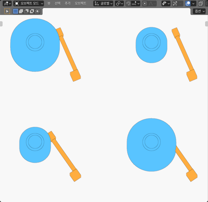
| Coil radius and catcher pose | Finite working-face result | Whole-core result |
|---|---|---|
| 35 mm coil, 35 mm pose | Edge projection inside the face; approximately 4.79 mm margin to its nearer width boundary | Numerically compatible support; no robust positive cross-core intersection |
| 55 mm coil, 35 mm pose | Working-plane gap approximately −20.00 mm | Both the head and arm intersect the coil envelope |
| 55 mm coil, 55 mm pose | Edge projection inside the face; approximately 4.12 mm margin to its nearer width boundary | Numerically compatible support; no robust positive cross-core intersection |
| 35 mm coil, 55 mm pose | Working-plane gap approximately +20.00 mm | Catcher separated from the smaller coil |
The swapped large-coil pose demonstrates the other failure: a face can have the right finite extent while the object remains separated from it. A wider head does not by itself close that gap. Conversely, enlarging the small-pose head would not remove the observed arm–coil intersection.
A positive signed working-plane gap means the coil lies away from the head’s n = 0 face. A negative value means the coil’s support extent crosses that plane. The approximately −20 mm value is a support-plane measurement; it is not a physical indentation, collision response or material penetration test. Closed finite-solid intersection was checked separately.
In the matched cases, the intended coil edge overlaps the face’s 16 mm axial extent. It is compatible with a line of support within the reconstruction band. We did not measure a positive-area contact patch or solve contact pressure. The neighbouring coil facets form a vertex normal cone; there is no single opposing planar coil face to compare with the head.
Distinguishing a finite match from an interference
We measured the full closed solids from Blender’s captured vertices and faces. The finite face/edge test and the whole-core intersection test were separate: a working-edge match could not excuse an interference elsewhere in the catcher. Repeated readings and an independent finite-solid calculation agreed on the four classifications.
The numerical checks used a 4 μm coordinate-correspondence bound, an 8 μm comparison band, an 8 μrad angular band and a 20 nm outward reserve. These bound this virtual reconstruction; they are not manufacturing clearances, positioning specifications or hardware safety margins. A gap within the comparison band means numerical compatibility, rather than exact physical contact.
What to carry into another model
Start by recording which dimensions belong to the part and which references belong to the pose. Here the arm remained unchanged, the pivot remained fixed, and the diameter-specific pose changed. Those conditions make the two swapped controls informative.
Then check the finite working surface and the full connected tool separately. A point or plane can be compatible while another member interferes. An apparently close screenshot can also conceal a gap or an embedded member. Keep the opaque geometry intact and use its coordinates to resolve hidden relations.
Our flat-faced cam follower study explores the related issue of a support point running beyond a finite face. The cable-drum radius study shows a different consequence of changing radius: length-per-turn calibration. The selective pallet engagement study applies a similar whole-core check to a target and its retained neighbours.
For a real wrapper, the next evidence would need to address the actual catcher geometry, a continuous reachable path, all surrounding equipment, paper interaction and validated physical behaviour. Our four static finite configurations establish none of those. They show why a diameter-specific pose deserves more than a check of the catcher tip alone.