A mould opening can accommodate a product while obstructing the gripper carrying it. In our Blender comparison, a 24mm-wide article fitted within a 30mm opening, but its 34mm gripping pad intersected both side members. A 40mm opening removed that interference at the same pose. Rotating the complete carried assembly then brought the pad into the left side again, despite keeping the wider opening.
The useful check is therefore the complete article-and-gripper geometry at a specified pose. We measured its projected footprint at the exit separately from its actual separation from the finite receiver members. Those two checks answered different questions, especially for the rotated carrier stem.
The process question behind the comparison
Whitech’s CWB 4 I pressure-casting description describes a module for two-part moulds. It assigns mould opening and handling, article demoulding and mould washing to the robot. This manufacturer description motivates checking opening and handling geometry together; it does not supply the dimensioned fixture used in our experiment.
We checked the official page on October 12, 2026, Korea time. Its publication and update dates were not identified. We did not operate this equipment or reproduce its CAD. Its advertised tilting capability is not the rotation tested below. Our independently dimensioned model isolates a clearance question, rather than evaluating the manufacturer’s machine.
Two connected assemblies around a real empty opening
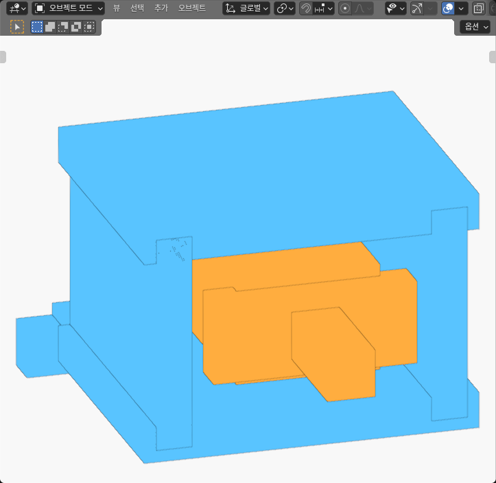
We built a blue receiver from seven closed members: two finite side halves, a roof, a floor, two rear legs and a rear yoke. The orange carried assembly contains three closed members: article, gripping pad and carrier stem. All ten members remain present in each configuration.
X measures opening width, Y points toward the front exit, and Z measures height. The exit plane is Y = 24mm. Its empty rectangular window is 28mm high, between Z = −14mm and +14mm. The side faces define either a 30mm or a 40mm width. We reconstructed this window from the four finite inner faces; no filled box stands in for the opening.
The following dimensions define the receiver. All intervals are in millimetres, measured in the configuration’s own datum. Here, s is 15mm for the narrow configuration and 20mm for the wide configurations.
| Receiver member | X interval | Y interval | Z interval |
|---|---|---|---|
| Left side half | [−s−6, −s] | [−24, 24] | [−18, 18] |
| Right side half | [s, s+6] | [−24, 24] | [−18, 18] |
| Roof | [−28, 28] | [−24, 24] | [14, 20] |
| Floor | [−28, 28] | [−24, 24] | [−20, −14] |
| Left rear leg | [−s−6, −s] | [−34, −22] | [−22, −14] |
| Right rear leg | [s, s+6] | [−34, −22] | [−22, −14] |
| Rear yoke | [−32, 32] | [−34, −28] | [−24, −16] |
Each side joins the roof, floor and its rear leg through positive virtual overlap. The legs overlap the rear yoke behind the exit. These connections establish a connected geometric receiver. They do not represent hinge kinematics, actuator travel, material bonding or joint strength.
The carried members use the following local intervals before applying their shared pose:
| Carried member | X interval | Y interval | Z interval |
|---|---|---|---|
| Article | [−12, 12] | [−14, 14] | [−9, 9] |
| Gripping pad | [−17, 17] | [12, 18] | [−7, 7] |
| Carrier stem | [−4, 4] | [16, 38] | [−4, 4] |
The article is 24 × 28 × 18mm. The pad is 34 × 6 × 14mm, and the stem is 8 × 22 × 8mm. The pad overlaps the article’s end interval by 2mm and the stem by 2mm. These intended overlaps connect the rigid virtual core; they are not measured pad compression, adhesion, suction or grip strength.
All three members share a translation of (0, 8, 0)mm. For the rotated comparison, we first rotate the whole local assembly about Z, then apply that translation. The rotation uses cosine 4/5 and sine 3/5, or approximately 36.87 degrees. No carried member moves independently or changes shape.
Changing opening and pose as separate comparisons
We first widened the receiver while holding the carried pose fixed. Each side half and its rear leg moved outward by 5mm, increasing opening width from 30mm to 40mm. This is a difference between constructed configurations, without an actuator-stroke measurement. We then kept the wide receiver and rotated only the complete carried assembly.
The results below are rounded from actual Blender coordinate readbacks and independently checked finite geometry. “Projected inside” requires the full footprints of all three carried members to have positive margins within the selected XZ window. It is an explicit criterion for this comparison, not a universal requirement for every possible removal sequence.
| Opening and carried pose | Full carried footprint projected inside? | Actual cross-assembly interference | Defined static geometry check |
|---|---|---|---|
| 30mm, unchanged pose | No: pad extends 2mm beyond each side | Pad intersects each side by about 112mm³ | Fails |
| 40mm, unchanged pose | Yes: minimum projected margin about 3mm | All 21 cross-assembly pairs strictly separated; minimum distance about 3mm | Meets both checks |
| 40mm, yawed about 36.87° | No: pad and stem extend beyond the left edge | Pad intersects left side by about 273mm³; stem remains separated | Fails |
“Meets both checks” means projected containment and finite solid separation at that static pose. It is not a successful extraction, a reachable robot pose or a safe operating condition.
The narrow opening exposes the product-only mistake
In the 30mm configuration, the article has approximately 3mm of projected space on each side and 5mm above and below. A width check using only the article would therefore look encouraging.
The pad changes the result. Its projected width is 34mm, so it extends roughly 2mm outside each side of the 30mm window. The finite solid calculation separately confirms positive virtual intersection with both side halves, about 112mm³ per side. This is interference in the constructed solids, not contact-force simulation or damage to a physical mould.
Widening the opening to 40mm at exactly the same carried pose gives the pad about 3mm per side. The article’s side margins increase to about 8mm. More importantly, every carried member is strictly separated from every receiver member: all 21 combinations were checked, including the roof, floor, rear legs and yoke. The smallest cross-assembly distance is approximately 3mm.
This comparison isolates the opening change. Removing the pad from the model, moving it separately, or changing the carried pose at the same time would answer a different question.
Rotation separates footprint overrun from actual collision
The article still projects inside the 40mm opening after the common yaw, with approximately 2mm remaining on each side. The pad’s leftmost projection, however, reaches about X = −24.4mm, extending roughly 4.4mm beyond the opening’s left edge. Its finite geometry intersects the left side by about 273mm³.
The carrier stem demonstrates why a projection alone is insufficient. It extends about 6mm beyond that same projected edge, reaching roughly X = −26mm, yet remains separated from the finite left side by approximately 2.4mm in 3D. Its position along Y matters: flattening the whole geometry onto the exit plane discards that information.
Thus, a negative projected margin identifies footprint outside the selected window. It does not, by itself, certify solid collision at the current pose. Conversely, checking only the article would miss the pad’s actual interference. Keep both the full carried footprint and each finite member pair in the analysis.
How we checked the constructed geometry
The three configurations contain 30 closed meshes, 240 actual world-coordinate vertices and 360 native triangles. We read complete authored and evaluated geometry, including faces, edges, normals and whole-member transforms. We computed all 45 distinct member pairs in each configuration, giving 135 comparisons: 63 across the two assemblies and 72 within them. Thirty prescribed positive overlaps confirmed the intended geometric connections across the three configurations.
The independent checks used finite solids and finite surface witnesses, rather than infinite planes or a fitted substitute shape. We also rotated the complete scene through a proper axis permutation, read it again, compared the recovered results and restored all 31 object matrices exactly. Separate inspection used a different finite polygon-clipping and distance calculation on the actual vertices. This provided a cross-check without reconstructing results from nominal dimensions alone.
The computation kept fixed checks of 4µm for coordinate correspondence, 8µm for comparisons, 8µrad for normal correspondence and a 20nm arithmetic reserve. These computational bounds are not manufacturing tolerances. An unresolved boundary would remain unresolved; none was left in these three configurations.
The displayed image is an untouched ordinary SOLID viewport capture. We used no rendering, cutaway, hidden member, transparency or edited image to make the assemblies appear to fit. A static image also cannot show every back surface, so it serves as an illustration of the constructed assemblies, rather than a substitute for the full geometry checks.
Apply the question to an actual handling design
Start with the product and every attached handling member in one specified pose. Define the finite receiver, opening amount and datum. Then ask two separate questions: does the selected exit footprint contain the complete assembly, and are the actual finite solids separated at this pose? When a check fails, identify the responsible member and its measured margin or intersection.
The keyed-joint release experiment studies release directions through a fixed receiver. This comparison changes the receiver opening before changing the carried pose. The slide-gate aperture comparison measures shared opening area between plates; that planar area does not establish clearance for a complete article-and-gripper assembly.
For a real demoulding decision, the next evidence would need to cover the continuous removal path, actual product and tool geometry, release forces, compliance and material behavior. We did not cast or wash an article, run a contact or force solver, test a controller, or operate hardware. The measured finding here is narrower: product-only width can miss the gripping pad, and an opening that clears the complete assembly at one pose can interfere with it after rotation.