Two individually plausible key joints can require incompatible movements when their keys belong to one rigid member. In our Blender study, translating a member with two parallel keys by 12 mm along X left both keys beyond their receiving openings. With perpendicular keys, the same X trial cleared one interface but put the other key through a wall; a Z trial exchanged those outcomes. The useful check was the complete two-interface assembly, not the key that appeared to come out first.
This is Physical AI Lab’s AI-assisted virtual assembly experiment, built and measured in Blender 5.2.2 LTS in October 2026. We constructed two connected functional cores, captured their actual native geometry and independently recalculated their finite clearances and intersections. These are four static geometry samples, not a simulated withdrawal trajectory or a physical woodworking test.
The reuse motivation comes from KIT’s ReFrame project description, which discusses wood-only connections and subsequent material use. That official page supplies context. Our rectangular keys, dimensions, movements and numerical checks are authored examples; they are not KIT joint geometry or evidence that its connections behave this way.
Build two connected cores, including the receiving walls
We used a blue receiving frame and an orange incoming member. Each receiver contains ten closed box meshes: a backbone, a bridge and two openings bounded by four finite walls each. Each incoming member contains three closed box meshes: its main body and two attached keys. The boxes within each core overlap at prescribed connections, so a key is part of its member rather than an independently movable object.
The first arrangement has two X-directed keys, placed at Y = −30 mm and +30 mm. The second keeps the negative-Y key along X but turns the positive-Y interface into a Z-directed key. Both keys remain attached to the same main body. Moving that body along one axis therefore moves the other key sideways relative to its own opening.
Here is the authored parallel arrangement before the prescribed translation. Every range is a closed solid’s minimum-to-maximum coordinate in millimetres, relative to that cell’s layout origin. For the four wall rows, the station variable s is −30 mm for the first opening and +30 mm for the second; each row is instantiated twice.
| Closed member | X range, mm | Y range, mm | Z range, mm |
|---|---|---|---|
| Receiver backbone | 0 to 12 | −48 to 48 | −14 to −6 |
| Receiver bridge | 10 to 22 | −48 to 48 | −14 to −9 |
| Opening bottom wall, each station | 0 to 12 | s − 10 to s + 10 | −8 to −0.6 |
| Opening top wall, each station | 0 to 12 | s − 10 to s + 10 | 10.6 to 16 |
| Opening lower-Y wall, each station | 0 to 12 | s − 10 to s − 5.6 | −1 to 11.6 |
| Opening upper-Y wall, each station | 0 to 12 | s + 5.6 to s + 10 | −1 to 11.6 |
| Incoming main body | 24 to 42 | −44 to 44 | 0 to 8 |
| Incoming negative-Y X key | 3 to 27 | −35 to −25 | 0 to 10 |
| Incoming positive-Y X key | 3 to 27 | 25 to 35 | 0 to 10 |
Each parallel opening has an empty interior X = 0 to 12, Y = s − 5.6 to s + 5.6, Z = −0.6 to 10.6 mm. Its four finite walls, including their corner connections, matter. Treating the whole receiving frame’s bounding box as solid would fill the very space that the key occupies.
For the perpendicular arrangement, the second key occupies X = 27 to 37, Y = 25 to 35, Z = −19 to 5 mm. Its receiving opening runs along Z from −22 to −10 mm, with interior X = 26.4 to 37.6 and Y = 24.4 to 35.6 mm. The left and right walls span X = 20 to 26.4 and 37.6 to 44; both span Y = 20 to 40. The lower- and upper-Y walls span Y = 20 to 24.4 and 35.6 to 40; both span X = 25.4 to 38.6. All four have Z = −22 to −10 mm. They join the same receiver through its bridge.
The perpendicular arrangement replaces only the second interface’s key and four walls. It is a different authored geometry, not a rotation performed during removal. We did not capture its unshifted datum as an additional observed state.
Compare four prescribed states using actual geometry
We created four complete assemblies: parallel keys engaged, parallel keys shifted +12 mm in X, perpendicular keys shifted +12 mm in X, and perpendicular keys shifted +12 mm in Z. The receiving core stays fixed within its cell, while every incoming mesh gets the same prescribed translation. No key moves independently.
For display, the second column is offset by 240 mm in X and the upper row by 200 mm in Z. Those offsets arrange the four examples in one viewport; they are subtracted when comparing assembly movements. Blender coordinates use metres, so the 12 mm trial is a 0.012 m translation. We retained the closed geometry and used an opaque SOLID editor capture.
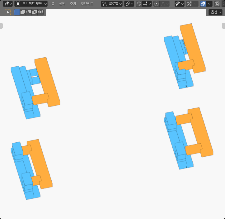
The four assemblies contain 52 closed meshes, 416 evaluated WORLD vertices and 624 native loop triangles. We took three full native geometry reads, including a distinct representative capture. A separate axis-permuted native capture tested the reader’s coordinate handling and was restored. Independent calculations checked the closed faces, connected-core witnesses, empty finite receiving interiors and every one of the 30 receiver-to-incoming solid pairs per cell.
The largest discrepancy between captured coordinates and the authored recipes was approximately 0.0000205 mm. Our 4 μm recipe correspondence bound, 8 μm comparison bounds and 20 nm arithmetic reserve are numerical checks. They do not specify acceptable woodworking tolerances. Forty deliberately corrupted copies of the actual capture were rejected by the independent reader; those checks concern this geometry evidence, not physical joint reliability.
Read both interfaces before accepting a release sample
The parallel engaged sample had approximately 9 mm of finite axial overlap at both keys. The nominal transverse gap was 0.6 mm on each side. All 30 cross-core pairs were disjoint: axial engagement means that the key extends through the opening’s length, not that it intersects the receiving material.
After the prescribed +12 mm X translation, both parallel keys had approximately 3 mm of axial end gap. Their positive axial overlaps were zero. Again, all 30 pairs were disjoint. The smallest key-to-receiver finite boundary distance was approximately 3.0594 mm, because the nearest wall boundary was also offset transversely. That distance is distinct from the 3 mm separation of the axial intervals.
The perpendicular trials produced a different assembly result:
| Captured state | X-directed interface | Second interface | Complete assembly result |
|---|---|---|---|
| Parallel, engaged | About 9 mm axial overlap | About 9 mm axial overlap along X | No strict cross-core intersections |
| Parallel, +12 mm X | About 3 mm axial end gap | About 3 mm axial end gap along X | No strict cross-core intersections |
| Perpendicular, +12 mm X | About 3 mm axial end gap | Z key intersects its right wall | One strict intersection, about 450 mm³ |
| Perpendicular, +12 mm Z | X key intersects its top wall | About 3 mm axial end gap along Z | One strict intersection, about 360 mm³ |
In the perpendicular X trial, the X key clears its finite opening length. The Z key still has approximately 9 mm of axial overlap, but the common X movement takes it sideways into the right wall. The actual overlap dimensions are approximately 5 × 10 × 9 mm, giving 449.9993 mm³ of common solid interior. The finite native boundary checks identify a point strictly inside both the key and the wall.
In the perpendicular Z trial, the Z key clears its finite opening length. The X key remains axially engaged by approximately 9 mm while moving upward into its top wall. The overlap dimensions are approximately 9 × 10 × 4 mm, giving 360.0009 mm³. We found exactly one strict cross-core intersection in each perpendicular sample after checking all 30 pairs, including the incoming body, receiver backbone and bridge.
These overlapping samples are prescribed positions of meshes. They are not positions reached by a physical mechanism passing through a wall. The experiment exposes an invalid candidate end state; it does not calculate the force that would be required to reach it.
Keep axial overlap, side clearance and solid distance separate
The clearest lesson was that a single overlap number can answer the wrong question. An axial interval check says whether a key still occupies the receiving opening’s finite length. A transverse section check says whether the key lies within the side boundaries at that section. A finite solid test says whether actual material intersects, or how far apart its real boundaries are.
For an axis-aligned example, signed axial overlap can be written as:
signed_overlap = min(key_end, opening_end) - max(key_start, opening_start)
engaged_length = max(0, signed_overlap)
axial_end_gap = max(0, -signed_overlap)
This is an explanatory interval calculation, not the complete validator we ran. It ignores the other axes, finite wall polygons, connected cores and the other interface. Extending a wall plane indefinitely also misses the difference between a finite opening end and the nearest material boundary.
The perpendicular X trial illustrates why these quantities must stay separate. Its Z key retains axial overlap but has a negative upper X section clearance of approximately −11.4 mm. That value is a section-boundary violation; it is not the penetration depth of a complete joint or a withdrawal-force estimate. The actual right-wall intersection is established separately from the complete finite solids.
Our earlier Oldham coupling engagement experiment examined sliding interfaces under prescribed offsets. This study asks a different question: can two keys attached to one member share a prescribed release movement? Likewise, the reclaimed-beam fit-up experiment concerns matching several interfaces by rigid placement; matching a placement does not establish a workable removal movement.
Use the result to choose the next investigation
For an assembly planner, the next useful input is a complete set of interfaces and a shared member transform. Checking one key and then independently checking the other at a different transform would accept motions that the connected incoming member cannot perform. Record each candidate movement, measure both interfaces and check the other receiving material before accepting its sampled state.
Our parallel sample supports a narrow conclusion: the prescribed +12 mm X end position clears both finite openings in this authored geometry. Our perpendicular samples show that the specified X and Z end positions each clear one key while intersecting a wall at the other interface. They do not prove global captivity, rule out a combined translation or rotation, or establish that no continuous removal route exists. That requires a path with intermediate poses and complete collision checks.
A physical wood-joint investigation would also need the actual connection geometry, grain and moisture conditions, dimensional variation, friction, fastener retention and permitted damage. A robot task adds grasp access, tool clearance, actuation limits and sensing. We did not execute contact physics, a release solver, a controller, hardware withdrawal or a material-recovery test. No load capacity, durability, safety or timber reuse rate follows from these samples.
The practical gain from this Blender experience is a better first geometry question: whether one candidate member movement satisfies every receiving interface together. The measured failures tell us which additional interface must enter the next investigation, before an apparently successful single-key withdrawal becomes an assembly-level assumption.