Removing a screw from its threads does not finish the removal problem. In this Blender experiment, both a 16 mm and a 30 mm rigid fastener envelope fit at the straight inlet of an authored passage. The 16 mm envelope also fit at the sampled bend pose. The 30 mm envelope did not: its head and shank extended outside the finite L-shaped void, and three fastener-to-wall pairs had strict common interior.
That result is deliberately narrow. It says that one complete rectangular envelope cannot occupy one static pose in one sharp rectangular surrogate passage. It does not say that a round screw will jam in a real hose or that suction could not find a different orientation.
A Fraunhofer IPA disassembly study reported manually removed screws from 4 to 30 mm long and noted that a future suction nozzle’s minimum bend radius depends on screw length to avoid blockage. The automated cell and its individual technologies remained future work. I used that requirement as motivation, not as geometry or operating validation. The paper is available from Fraunhofer.
The centreline was never the acceptance test
A line can turn through a corner while the body around it clips the inside or outside wall. That matters after disengagement because the transported object still includes a head and a shank. A check based on the shank axis alone discards the widest part of the object.
I therefore asked whether every point of both solids occupied the complete finite empty passage at each sampled pose. I also checked each solid separately against every guide member. These are related tests, but they answer different questions. A body may lie partly outside the intended void even when an isolated wall-pair test looks clear, while a strict common-interior point gives direct evidence that two authored solids overlap.
The same separation appears earlier in a screw-removal workflow. Whole-driver access through an enclosure concerns the tool before removal. Blind-hole bottoming and head seating concerns the installed screw. The retracted screwdriver envelope concerns whether the loaded fastener is contained by or exposed from a straight tool. Here the fastener is already detached and is being checked against a separate bent passage.
I used a sharp rectangular surrogate on purpose
The guide is an independently authored L-shaped passage with a 10 × 10 mm empty section. Eight closed solids form its inlet and outlet walls, roofs, and floors. Their overlaps make one virtual guide assembly; they do not represent welds, seals, or structural strength.
The fastener is another intentionally simple envelope. Its head has a 7 × 7 mm section and is 4 mm long. Its shank has a 3 × 3 mm section. The two members overlap axially by 1 mm so they move as one virtual rigid body. I compared total lengths of 16 and 30 mm while keeping those sections unchanged.
This is not a circular screw, a rounded nozzle, a flexible hose, or a bend-radius model. The sharp inside corner makes the finite-body issue easy to isolate. It would be misleading to transfer the measured clearances to a real product or use them to select a hose radius.
I authored four independent static cells in AI-operated Blender 5.2.2 LTS. At the inlet, the body midpoint was (0, -22) mm and its axis followed the straight leg. At the bend, the midpoint was (3.5, -3.5) mm and the body was turned 45°. Length was the controlled change within each station.
For reproduction, these are the authored guide bounds in millimetres in one station frame. The finite inlet ends at Y = −42 and the outlet ends at X = 42; the empty section has Z from −5 to 5. The roofs stay in place during both calculation and screenshot capture.
| Guide member | X interval (mm) | Y interval (mm) | Z interval (mm) |
|---|---|---|---|
| Outer inlet wall | −7 to −5 | −42 to 7 | −7 to 7 |
| Inner inlet wall | 5 to 7 | −42 to −5 | −7 to 7 |
| Outer outlet wall | −7 to 42 | 5 to 7 | −7 to 7 |
| Inner outlet wall | 5 to 42 | −7 to −5 | −7 to 7 |
| Inlet roof | −7 to 7 | −42 to 7 | 5 to 7 |
| Inlet floor | −7 to 7 | −42 to 7 | −7 to −5 |
| Outlet roof | −7 to 42 | −7 to 7 | 5 to 7 |
| Outlet floor | −7 to 42 | −7 to 7 | −7 to −5 |
Before rotation, let total envelope length be L along local X. The head occupies X from L/2 − 4 to L/2 and Y and Z from −3.5 to 3.5 mm. The shank occupies X from −L/2 to L/2 − 3 and Y and Z from −1.5 to 1.5 mm. Thus the head sits at the positive-axis end and overlaps the shank by 1 mm. Both members receive the same 90° inlet or 45° bend rotation about Z and the same midpoint translation. The 45° input uses the literal matrix coefficient 0.7071067811865476; evaluated Blender coordinates are finite precision.
I displayed short inlet, long inlet, short bend and long bend cells at additional XY offsets of (0, 0), (120, 0), (0, 120) and (120, 120) mm. Each offset moves both cores equally and is removed for measurements. These layout offsets are not a travelled route.
Three sampled poses cleared; the long bend did not
The evaluated geometry produced an unambiguous split:
| Sampled state | Envelope | Complete passage occupancy | Fastener-to-guide result |
|---|---|---|---|
| Straight inlet | 16 mm | Fully contained | All wall pairs separated |
| Straight inlet | 30 mm | Fully contained | All wall pairs separated |
| Bend at 45° | 16 mm | Fully contained | All wall pairs separated |
| Bend at 45° | 30 mm | Not fully contained | Three strict interior intersections |
The short bend case was the useful control. Its complete head and shank stayed inside the finite void rather than merely keeping their centre points inside. The minimum finite XY boundary distance was about 0.368 mm for the head and 0.621 mm for the shank. The head also retained about 1.50 mm of Z margin. Those are evaluated geometric distances in this model, not recommended production clearances.
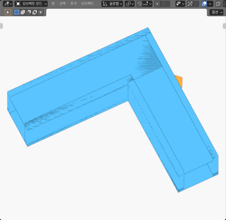
The long bend case failed both parts of the check. The complete head and shank were not contained by the L-shaped void. The independent finite-solid classification also found strict common-interior points for these three pairs:
- outer inlet wall and shank;
- outer outlet wall and shank;
- outer outlet wall and head.
A strict interior certificate means the two evaluated solids share interior at that pose. It does not provide penetration depth, contact force, blockage severity, or a sum that can be interpreted as displaced material. I have therefore left intersection volumes out of the reader result.
No case landed in an unresolved numerical boundary band. The calculation used fixed numerical consistency bounds, but those bounds describe the geometry check. They are not manufacturing tolerance, scanner accuracy, or evidence of sub-millimetre hardware performance.
Static occupancy is not a transport path
The four cells are separately authored poses. They are not frames from a simulated motion, and the clear samples do not connect themselves into a valid route. In particular, the 16 mm body being clear at the bend does not prove that it can travel from the inlet to that pose without touching a wall. The first interference angle between samples is also unknown.
A proper evacuation study would need a declared route class and more poses, or a continuous collision method that treats translation and rotation together. A physical study would add object shape variation, gravity, airflow, friction, impacts, tumbling, flexible hose motion, and retention. None of those effects were represented here.
The experiment also says nothing about whether a suction system can acquire the screw, whether it remains attached to an airflow stream, or whether the disassembly tool has fully released it. “Disengaged” is only the starting condition for this geometry question.
What I would change before testing transport
The practical lesson is to keep screw release and evacuation clearance as separate gates. For a proposed fastener set, define a conservative complete envelope, the actual passage void, its finite end planes, and the allowed orientation at the bend. Then test the whole body against the whole guide. Do not accept a valid centreline or one inside-corner point as proof.
If the long envelope fails, the next design move depends on the system. The passage section could change, the corner could be rounded or enlarged, the permitted orientation could be constrained, or a different removal route could be chosen. Any modified geometry needs its own full check; this experiment did not test those alternatives.
For this authored comparison, length did not matter at the straight sample but changed the answer at the bend. That is enough to reject a fixed “disengaged means removable” assumption. It is not enough to declare a universal length limit. The result belongs to the stated envelope, passage, and pose—and that is exactly the level at which the next design decision should be made.