Two interfaces can have the same rounded support percentage and still present different geometric conditions. In this Blender experiment, a blind groove and a through seam both retained 99.5% of the square head’s projected bearing field when rounded to one decimal place. The blind groove still left a complete covered barrier around the inner opening. The through seam created a complete positive-width uncovered corridor from that opening to the exterior.
That is the practical answer: when an interface depends on separation around an opening, measure coverage and connectivity separately. A single percentage can hide the feature that matters.
I examined four independently authored static cells in an AI-operated Blender 5.2.2 LTS model. They compare the same finite square head with a solid coupon, a blind radial groove, a through seam, and a groove outside the bearing field. This was a virtual geometry study, not a physical suction-head trial or a continuous placement simulation.
Fraunhofer IFAM describes sealing at the head-to-surface interface and a defined inner-nozzle spacing. That motivates checking the whole interface. The source does not provide this model’s dimensions, groove layouts, tolerances, pressure, or performance. The page was checked on October 12, 2026.
Coverage and connectivity answer different questions
Coverage measures how much of the projected bearing field remains over coupon material. Connectivity asks how the missing part is arranged.
For this experiment, H is the union of the complete lower cap projections from the four head members. C is the union of the complete top-interface cap projections from the coupon members. Their intersection, B = H intersect C, is the projected supported field. The finite domain, Ω, is the complete base projection, X and Y from -40 to +40 mm. The chamber is the inner component of Ω minus H; the exterior is the component reaching the coupon boundary. I tested their connection through Ω minus B, not through three-dimensional empty space.
The classification then asks two whole-field questions. First, does B contain a complete positive-width covered barrier around the head’s inner chamber? Second, does the missing-support region contain a complete positive-width corridor from that chamber to the declared exterior?
Those tests cannot be replaced with a few sample points. A narrow corridor can pass between samples, while an almost closed strip can fail to form a barrier. They also cannot be inferred from pixels or a bounding box. The complete finite cap arrangement has to be evaluated.
The words “barrier” and “corridor” describe planar geometry here. They do not establish an airtight seal, leakage route, or airflow behavior.
The model keeps both cores finite
The head core is a square perimeter head made from four connected closed boxes. Its outer boundary is 60 × 60 mm and its inner opening is 40 × 40 mm. The left and right bars span Y from -30 to +30 mm and occupy X from -30 to -20 mm and +20 to +30 mm. The lower and upper bars span X from -30 to +30 mm and occupy Y from -30 to -20 mm and +20 to +30 mm. All four extend from Z = 1 to 5 mm.
The fixed core is an 80 × 80 mm coupon. Its base spans X and Y from -40 to +40 mm and Z from -4 to -2 mm. The top-interface pieces extend from Z = -2.2 to 0 mm, overlapping the base by 0.2 mm so each coupon remains one connected virtual assembly.
The solid coupon has one complete top. In the blind-groove case, the left and right top pieces still span the full Y range of -40 to +40 mm, while the slabs below and above the groove cover X from 14.8 to 25.2 mm. In the through-seam case, those below and above slabs extend across X from 14.8 to 35.2 mm. The outside-groove case puts its below and above pieces at X = 34.8 to 40 mm, outside the head’s projected bearing band. These overlaps connect the coupon members without filling the declared missing top region.
The following nominal intervals finish the recipe. Every interval is in the common coupon frame; all listed top pieces share Z = -2.2 to 0 mm. “Below” and “above” refer to the Y direction.
| Coupon case | Missing top region X, Y (mm) | Complete side pieces X (mm), full Y = -40 to +40 | Below/above pieces: X; Y intervals (mm) |
|---|---|---|---|
| Solid | None | One top: X = -40 to +40 | Full Y = -40 to +40 |
| Blind | X = 15 to 25; Y = -1 to +1 | Left = -40 to 15; right = 25 to 40 | X = 14.8 to 25.2; Y = -40 to -1 and +1 to +40 |
| Through | X = 15 to 35; Y = -0.5 to +0.5 | Left = -40 to 15; right = 35 to 40 | X = 14.8 to 35.2; Y = -40 to -0.5 and +0.5 to +40 |
| Outside | X = 35 to 40; Y = -0.5 to +0.5 | Left = -40 to 35; no right piece | X = 34.8 to 40; Y = -40 to -0.5 and +0.5 to +40 |
For display only, I translated the solid, blind, through and outside cells by XY offsets of (0, 0), (180, 0), (0, 180) and (180, 180) mm. Both cores share each offset, which is removed before measurement. These are four static poses; the head does not travel between them.
The coupon base is real geometry, but its face at Z = -2 mm is not the top reference plane used to construct C. Treating the base as top support would erase every groove. The head’s lower faces remain at Z = 1 mm, so every cell retains an evaluated gap of about 1.00 mm above the coupon top. The model therefore makes no contact or sealing claim.
Similar rounded coverage produced different fields
The authored nominal construction gives both the blind and through cases 1,990 mm² of support from a 2,000 mm² bearing field, or exactly 99.5%. The evaluated Blender coordinates were stored as finite floating-point geometry, so the raw areas are close rather than exactly equal.
| Static case | Evaluated B area (mm²) | Raw coverage | Complete field certificate |
|---|---|---|---|
| Solid interface | 1,999.999911 | 100.000000% | Covered barrier; no corridor |
| Blind radial groove | 1,990.000411 | 99.499999% | Covered barrier; no corridor |
| Through bearing seam | 1,990.000561 | 99.500007% | No barrier; positive-width corridor |
| Groove outside bearing | 2,000.000954 | 100.000000% | Covered barrier; no corridor |
The 0.000150 mm² raw difference between the two grooved cases is a numerical consequence of the evaluated coordinates, not a meaningful physical advantage. Both reasonably report as 1,990.00 mm² and 99.5% for this comparison.
The conservative outward coverage intervals were much broader: about 89.16–100% for the blind groove and 89.00–100% for the through seam. Those bounds overlap almost completely. They are useful evidence that the rounded percentage cannot carry the decision, but they do not weaken the separate topology result. The complete finite arrangement certified a closed covered barrier for the blind case and a positive-width chamber-to-exterior corridor for the through case. No boundary case remained unresolved. These deliberately broad area intervals include conservative boundary allowances for all cap triangles. They are not a claim of physical measurement precision; the six-decimal raw values in the table only distinguish the captured floating-point geometry.
The solid and outside-groove cells provide useful controls. Both retained complete coverage and a closed barrier. Moving a groove outside H did not subtract support merely because it remained part of the larger coupon geometry.
Why the whole-field certificate matters
An area-only rule would treat the blind and through cases as equivalent after ordinary rounding. A point-sampling rule could also miss the through seam if none of its points landed inside the narrow uncovered strip.
The actual check instead used all evaluated head and coupon cap boundaries. It partitioned the finite projected domain at the relevant edges, then tested the complete covered and uncovered regions. A barrier required positive width all the way around the opening. A corridor required positive width all the way from the chamber side to the exterior. Exact-boundary uncertainty would have remained a HOLD rather than being promoted to either result.
For an explicit certificate, I tested four whole 1 mm strips between an outer square with X/Y limits ±28 mm and an inner square with limits ±27 mm. Their corners overlap with positive area. In the blind case all four strips are covered by B and separate the entire chamber from the exterior. The through case instead admits the whole rectangle X = 18 to 32 mm, Y = -0.25 to +0.25 mm inside Ω minus B, with positive overlaps into both regions. Its half-width clearance from B is about 0.249994 mm; the blind barrier’s nearest missing-support boundary is about 1.999994 mm away. Both exceed the propagated digital boundary allowance of approximately 0.024533 mm. That margin supports the separate field decisions despite the loose area bounds.
I read back all 32 closed meshes, 256 evaluated world corners and 384 native triangles. The complete 115 material-pair tests and 28 positive-overlap links confirmed that each head and coupon formed a connected virtual core. Repeating the actual reads in solid/through/solid order and under a proper axis permutation preserved the results within the fixed bounds. This verifies the static digital geometry, not physical assembly performance.
This reader job differs from the slide-gate aperture experiment, which measured the common open area between two translated apertures. It also differs from the sandwich closure experiment, which checked whether a prescribed cut segment stayed inside a shared footprint. The flat-faced cam follower experiment followed one finite support edge. Here the decisive object is the connectivity of the complete supported and unsupported interface fields.
The numerical coordinate and comparison bounds used to classify the mesh are consistency controls for this digital experiment. They are not manufacturing tolerances, surface-flatness limits, or estimates of physical accuracy.
Turn the result into a design check
Start by naming the regions that the interface must keep separated. Then construct the complete projected bearing field from the actual finite faces, subtract the missing-support region, and measure both area and connectivity.
If the requirement is a closed perimeter, record the minimum acceptable barrier width and test that barrier directly. If an exterior connection is unacceptable, test for a complete positive-width corridor instead of relying on total coverage. A design review can then distinguish a blind recess from a through seam even when their areas round to the same value.
Changing the head width, opening size, groove width, or groove endpoint can change both results, so each proposed geometry needs the same finite-field check. The current four static cells do not establish a worst case or a continuous placement range.
This experiment does not test pressure, suction, leakage, airflow, abrasive recovery, compliance, roughness, deformation, approach motion, hardware, process quality, or safety. The coupon base two millimetres below the top plane does not turn a projected corridor into a verified three-dimensional flow passage. Physical interface behavior requires its own model and test after the geometry rule has been chosen.
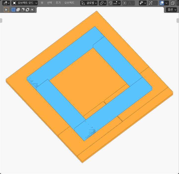
The groove is visible only where the orange coupon remains exposed. The head conceals the interface below it, and the stippled coplanar corner overlaps remain in the original pixels. All measurements and field classifications above come from evaluated finite geometry, not from the screenshot.