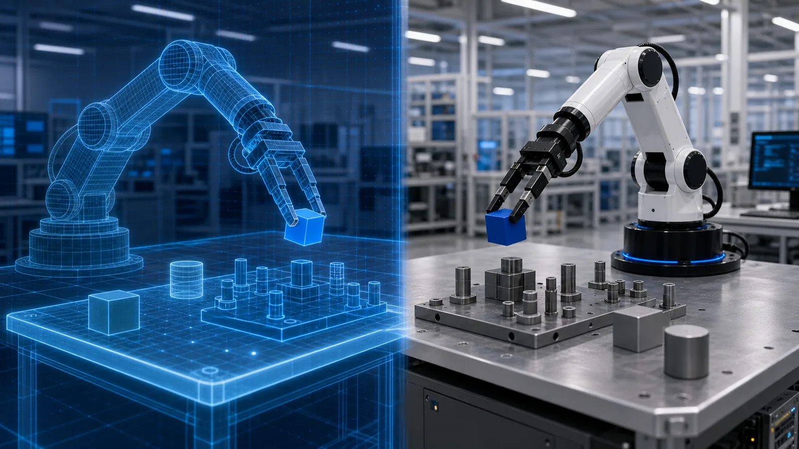
Sim-to-real transfer is the process of training or testing robot behavior in simulation and then making it work on physical hardware. Simulation can generate experience faster, cheaper and more safely than real robots, especially for collisions, resets and rare conditions.
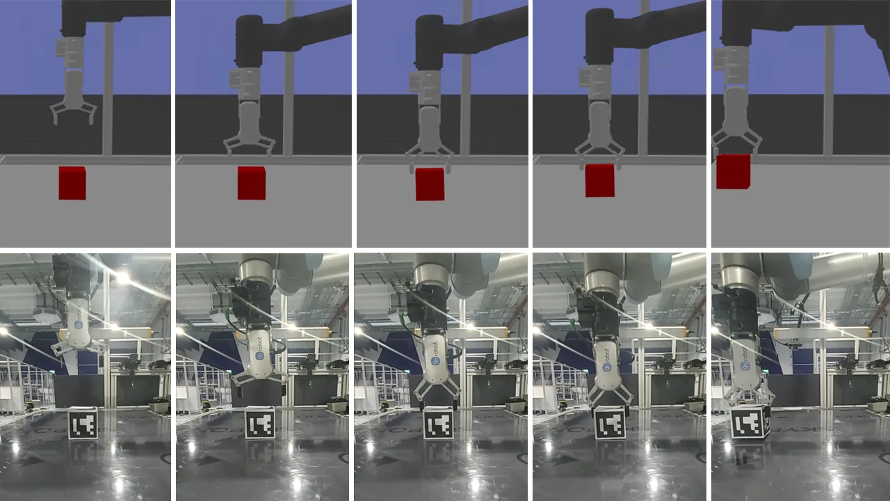
Transfer fails when the simulated observations and dynamics differ in ways the policy relies on. A camera texture may change, a joint may respond more slowly, or contact friction may place an object outside the learned trajectory. These differences are collectively called the reality gap.
The practical goal is not a perfect digital copy of the world. It is a simulation and training distribution accurate and varied enough that the policy remains stable inside the real operating envelope.
What sim-to-real means
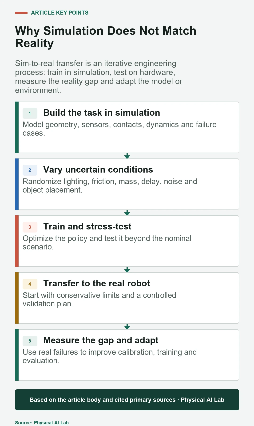
A sim-to-real workflow defines a robot, task and environment in a simulator; trains or validates a policy; deploys a constrained version to hardware; measures mismatches; and updates models or training distributions. Each hardware test should answer a transfer question rather than serve as a final demo.
The approach supports physical AI because real data is expensive and safety-critical exploration is limited. Simulation expands coverage, while hardware evidence remains the final test of physical performance.
The reality gap has several layers
Visual gaps include textures, shadows, exposure, lens distortion and sensor noise. Dynamics gaps include mass, friction, backlash, compliance and actuator response. System gaps include delays, dropped frames, calibration drift and differences between simulated and real controllers.
A policy can overfit any of these shortcuts. If a simulated highlight always marks the target, randomizing object color may not fix the problem. Transfer debugging starts by identifying which observation or dynamic variable changed the action.
| Gap | Examples | Typical countermeasure |
|---|---|---|
| Visual | Lighting, texture, camera noise | Randomization, augmentation, real images |
| Geometry | Dimensions, pose, collision mesh | Measurement and bounded variation |
| Dynamics | Mass, friction, damping, compliance | System identification and parameter ranges |
| Timing | Inference, network and actuator delay | Latency modeling and hardware-in-the-loop |
Start with coordinate frames and units
Before tuning a learning method, confirm joint order, sign conventions, units, transforms and reset states. A centimeters-versus-meters error or a camera transform offset can look like a policy failure while no amount of retraining will correct it reliably.
Run simple hardware checks: command known poses, compare measured and simulated end-effector positions, and replay low-speed trajectories. These tests create a trusted foundation for later learning experiments.
Also check whether the calibration motions can reveal the parameter you want to estimate. In the pure-translation hand-eye example, different camera offsets satisfy the same relative-motion equations: a zero residual does not identify the offset. This is a synthetic geometric example of observability, not a measurement of real calibration accuracy.
System identification estimates the parameters that matter
System identification uses measured input-output data to estimate masses, friction, motor response, delays or other model parameters. The objective is task relevance, not reconstructing every physical detail.
Excite the system inside safe limits and record synchronized commands and observations. Fit parameters on one data set and validate on another. A model that matches only the calibration trajectory may not predict task motion.
Domain randomization trains for a distribution
Domain randomization research varies selected simulation parameters across episodes so the policy cannot depend on one exact world. Useful ranges can include camera pose, lighting, object mass, friction, controller gains and latency.
Ranges should be wide enough to cover expected variation but not so broad that learning becomes unstable or the policy sacrifices useful performance. Real measurements provide a center and plausible bounds; randomization is not a substitute for calibration.
Observation and action design affect transfer
Policies that depend on perfect simulator state may fail when real sensing is noisy or unavailable. Train with observations the deployed system can produce and inject realistic delay, dropout and quantization. Privileged simulator state can still train a critic or teacher if the deployed policy does not require it.
Action representations also matter. A VLA policy predicting end-effector deltas may transfer differently from a torque policy. The simulator controller and hardware controller should expose comparable behavior at the policy interface.
Residual learning and real-world correction
Residual methods keep a stable nominal controller and learn a smaller correction. This can reduce the search space and retain known constraints. The correction still needs limits so it cannot overwhelm the baseline when observations leave the training distribution.
A small amount of real data can also fine-tune perception or policy behavior after simulation pretraining. Collect corrections from representative failures, keep a held-out hardware test set, and guard against improving one condition while degrading another.
Hardware-in-the-loop finds integration gaps early
Hardware-in-the-loop testing inserts real controllers, sensors or compute into a simulated task. It exposes message timing, saturation, clock alignment and driver behavior without requiring the complete physical setup for every test.
It is especially useful for worst-case latency and fault injection. Teams can delay observations, drop packets or freeze a sensor and verify that the system enters the intended safe state before full robot trials.
A staged real-world validation plan
Begin with low speed, reduced force, light payloads and clear space. Validate initialization and stopping before task success. Increase one risk dimension at a time while keeping the previous acceptance tests.
Record every attempt, including resets and human intervention. Compare simulation and hardware distributions for observations, actions and outcomes. The goal is to locate systematic mismatch, not to obtain a single successful run.
- Stage 1: static calibration and known-pose checks.
- Stage 2: open-loop and low-speed trajectory comparison.
- Stage 3: closed-loop task with reduced speed and payload.
- Stage 4: disturbances and edge cases inside the approved envelope.
- Stage 5: repeated endurance runs with intervention tracking.
Metrics that reveal transfer quality
Report success rate in simulation and reality, but also the transfer ratio, completion time, tracking error, intervention rate and safety stops. A small success gap can hide a large difference in smoothness or support burden.
Slice results by object, pose, speed, payload and environmental condition. Confidence intervals and repeated runs help distinguish systematic improvement from trial-to-trial luck.
| Metric | What it reveals | Caution |
|---|---|---|
| Real task success | Operational outcome | Needs enough independent trials |
| Sim-real trajectory error | Dynamic mismatch | May not predict task success alone |
| Intervention rate | Human support burden | Define intervention consistently |
| Recovery rate | Robustness after disturbance | Separate autonomous and assisted recovery |
Common failure patterns and fixes
If motion is consistently offset, inspect calibration and frames. If it oscillates or overshoots, inspect timing, controller gains and actuator dynamics. If vision fails under specific lighting, compare real image statistics and augmentation coverage.
If performance varies between runs, check reset consistency, temperature, battery state and unmodeled contact. Fix deterministic integration errors before adding more randomness or more training data.
How to judge a sim-to-real claim
Ask how many physical trials were run, which simulator parameters were randomized and what real data entered the loop. For a broad robot foundation model, confirm whether transfer was demonstrated across tasks, robots or only repeated conditions.
Strong evidence includes the evaluation protocol, failed trials, hardware configuration and operating limits. A visual side-by-side comparison is useful context, not a substitute for quantitative results.
Frequently asked questions
What is the reality gap in robotics?
It is the difference between simulated and physical observations, dynamics, timing and system behavior that can cause a policy to fail after deployment.
Is domain randomization always required?
No. Accurate modeling, real-data adaptation, residual control and robust classical methods can also support transfer. The right combination depends on the task.
How much real-world data is needed?
There is no fixed amount. Collect enough representative trials to calibrate important parameters and estimate performance with uncertainty across the intended operating envelope.
Can a policy transfer without fine-tuning?
Yes, zero-shot transfer is possible when training variation and interfaces cover the real system. It must still be validated on hardware.
Which simulator is best for sim-to-real?
Choose based on the required contacts, sensors, speed, robot support and reproducibility. Workflow quality and validation matter more than a simulator name.
What Transfer Evidence Should Include
Hardware testing can create collision and equipment risks. Use task-specific limits, supervision and risk controls during every transfer stage.