Sim-to-real transfer fails when the observations and consequences experienced by a real robot differ enough from those used in simulation that the learned policy chooses the wrong action. The mismatch is not one mysterious reality gap. It can be decomposed into visual, sensor, dynamics, control and task gaps that require different measurements and remedies.
A policy may grasp perfectly in simulation but miss on hardware because the camera is shifted, contact friction is wrong, the controller is delayed or the object starts outside the training distribution. Adding more randomization without locating the cause can make training harder while leaving the dominant failure untouched.
The practical workflow is to reproduce the failure, compare synchronized simulation and hardware traces, isolate the earliest divergence, change one uncertainty model and repeat the same evaluation. Successful transfer is evidence from controlled real-robot trials, not visual similarity or a single demonstration.
Split the reality gap before choosing a fix
The phrase reality gap is useful only as a starting label. A debugging record should identify which observed variable first diverged: image features, sensor state, contact, joint response, timing or task context. That variable points toward calibration, model identification, randomization, control or dataset changes.
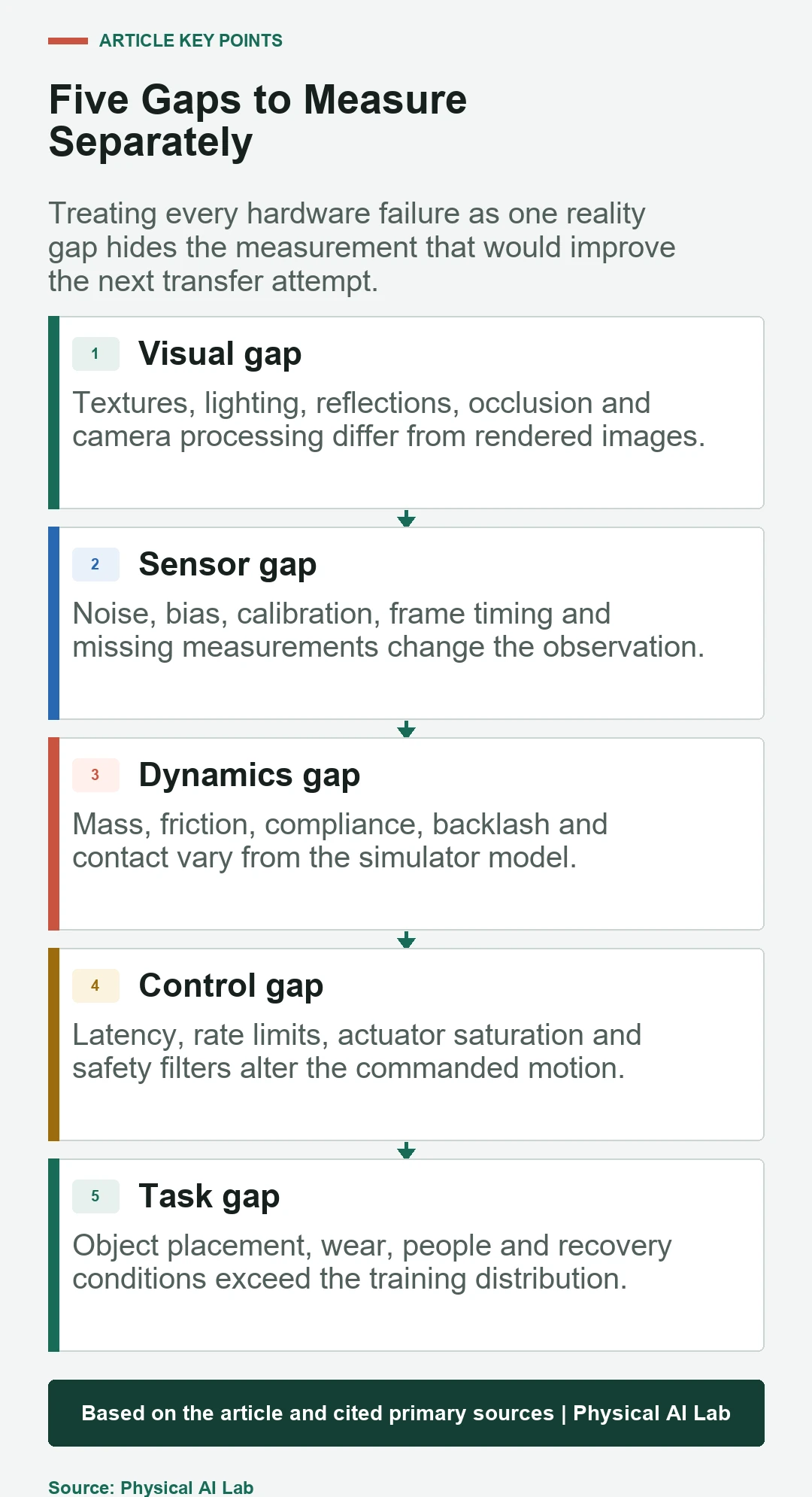
The five-gap card provides a diagnostic map. Several gaps can interact, but measuring them separately prevents a visual remedy from being applied to a dynamics problem or a broader dataset from masking a controller-rate issue.
Visual gaps change what the policy thinks it sees
Rendered lighting, texture and reflections rarely match a real camera. Lens distortion, exposure, motion blur, compression and partial occlusion can alter features further. A policy trained on clean object boundaries may fail when transparent, metallic or deformable objects appear under mixed lighting.
Measure the visual gap with paired or comparable scenes. Check detection and segmentation before evaluating the complete task. Domain randomization, photorealistic rendering, real-image fine-tuning or appearance translation can help, but each should be tied to an observed failure mode.
Sensor gaps include calibration, noise and time
Depth cameras, force sensors, encoders and inertial sensors produce bias, dropout and quantization that may be absent or simplified in simulation. Camera-to-robot calibration can shift a target by centimeters even when the perception model is correct. Timestamp errors can combine measurements from different physical moments.
Log raw sensor messages and calibration versions. Compare noise distributions, missing-data patterns and frame timing between simulation and hardware. Inject measured noise and delay rather than choosing arbitrary values, and retain an out-of-family test so the policy is not tuned only to one robot.
Dynamics gaps appear at contact
Mass, center of gravity, friction, stiffness, damping, backlash and actuator saturation determine how commands become motion. Contact-rich tasks amplify small errors because a different surface normal or compliance changes the force and future state. Rigid simulation can overestimate repeatability for soft or irregular objects.
Use system identification where measurements are available. Estimate actuator response, payload, friction and delay from hardware traces, then test whether the simulator reproduces those traces. Randomize residual uncertainty around measured values instead of replacing calibration with a very wide distribution.
| Gap | Observable symptom | First measurement |
|---|---|---|
| Visual | Wrong object or pose before motion | Perception output on matched scenes |
| Sensor | State jumps, bias or inconsistent geometry | Raw signal, calibration and timestamps |
| Dynamics | Trajectory diverges after contact | Commanded versus measured motion and force |
| Control | Overshoot, oscillation or late correction | End-to-end latency and control rate |
| Task | Failure only in new layouts or objects | Coverage of the training and test distributions |
Control gaps change even a correct policy output
A simulation may apply an action at an exact rate with no communication jitter. Real systems have inference time, network delay, controller queues, safety filters and motor limits. The physical command can therefore arrive late or be clipped, producing an observation that the policy never encountered during training.
Measure the complete sense-to-act latency and its distribution, not just average model inference. Replay real timing in simulation, test rate limits and saturation, and verify that safety controls do not create hidden discontinuities. A lower-level tracking controller should also be validated independently of the learned policy.
Task gaps come from the operating environment
Real work introduces object wear, unexpected placement, people, clutter, changing payload and incomplete resets. A policy can cross the visual and dynamics gap for one prepared scene yet fail when the task distribution expands. That is a coverage problem rather than a simulator-fidelity problem.
Define the operating envelope before training: objects, poses, lighting, surfaces, payloads, human proximity and allowed disturbances. Evaluate inside and just outside the envelope. The boundary shows whether the next improvement should expand data, constrain deployment or add a recovery procedure.
Domain randomization should follow measured uncertainty
Domain randomization exposes a policy to varying appearance or physics so it relies less on one simulated configuration. NVIDIA’s Isaac Sim documentation shows how visual properties can be randomized for synthetic data generation.
Randomization is not a substitute for diagnosis. If ranges are too narrow, the real system remains out of distribution. If they are too wide, the policy may become conservative or fail to learn useful structure. Start from measured variation, then include plausible tail conditions and hold out combinations for evaluation.
Appearance transfer solves only part of the problem
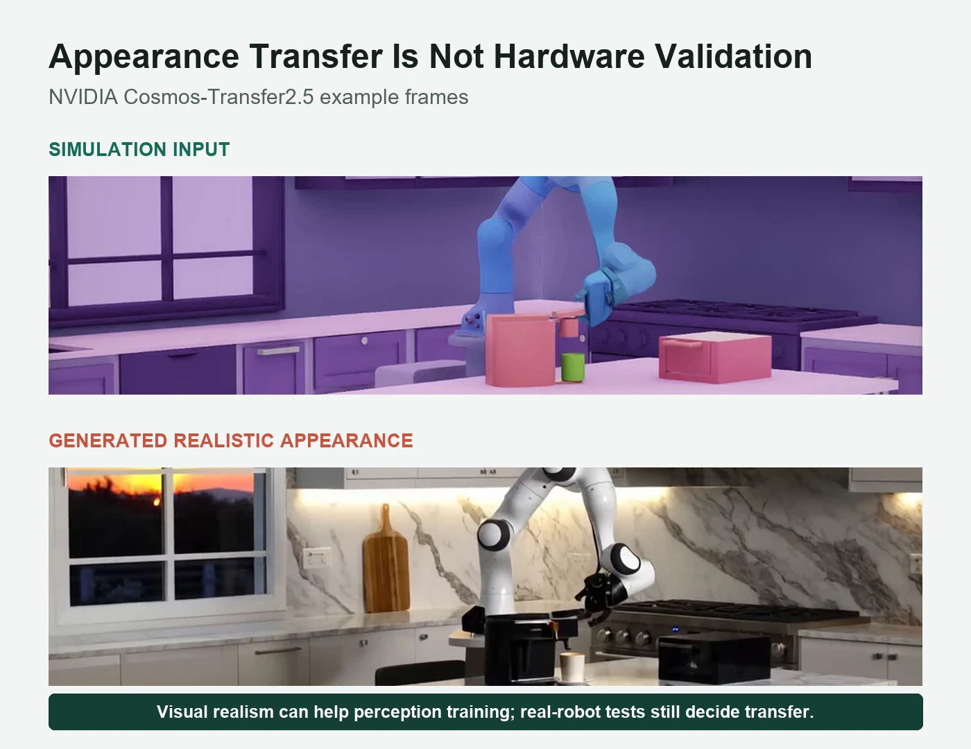
Generative appearance transfer can make a rendered scene look more like real camera data. The NVIDIA Cosmos-Transfer2.5 simulation-to-real example illustrates a simulation frame and a generated realistic output. This can be useful for perception training and visual variation.
The generated frame is not a hardware test. It does not prove that contact, actuator response, latency or recovery matches reality. Keep appearance augmentation and real-robot validation as separate evidence layers so a realistic image is not mistaken for successful transfer.
Real-robot evaluation must reveal the failure distribution
The sim-to-real transfer guide covers the complete workflow; failure analysis adds a stricter reporting requirement. Count all trials, define success before testing, record interventions and group failures by their first observable cause. A highlight reel cannot support a transfer rate.
Use repeated initial states and a separate variation set. Report confidence intervals when trial counts permit, and preserve failed traces. The table distinguishes evidence that supports a transfer claim from signals that should trigger another test.
| Evidence item | Useful report | Weak report |
|---|---|---|
| Trial population | All attempts and predefined success rule | Selected successful clips |
| Variation | Named objects, poses, lighting and disturbances | Claims of novelty without a split |
| Intervention | When, why and how often people took over | Assistance omitted |
| Failure trace | Earliest divergence and synchronized logs | Single label such as reality gap |
A repeatable debugging workflow
Freeze the policy and reproduce one failure safely. Align simulation and hardware logs on observation, action and time. Find the earliest variable that leaves the expected range. Change one model or randomization family, rerun the same test set and confirm that the targeted failure decreases without creating a new dominant failure.
Keep deployment limits conservative during this loop. Physical AI systems must contain uncertainty with safety controls and human escalation while learning components improve. The goal is not to prove that simulation is perfect; it is to produce evidence that the real system works within a defined envelope.
- Reproduce the real failure with synchronized logs.
- Locate the earliest visual, sensor, dynamics, control or task divergence.
- Change one uncertainty model or calibration at a time.
- Retest the same variation set and check for regressions.
- Expand the operating envelope only after evidence improves.
Frequently asked questions
Why does a robot work in simulation but fail in reality?
The real observations and action consequences differ through camera appearance, sensor noise, calibration, contact physics, latency or task variation. The first divergent signal should be measured.
Does better photorealism solve sim-to-real?
Not by itself. Photorealism can reduce a visual gap, but sensor timing, dynamics, control, contact and task coverage still require measurement and hardware tests.
What is the difference between system identification and domain randomization?
System identification estimates model parameters from hardware data. Domain randomization trains across a distribution of uncertain values. They work best together.
Should every simulator parameter be randomized?
No. Randomize parameters that are uncertain and materially affect the task. Excessively broad or irrelevant variation can reduce learning efficiency and hide the real cause.
How many real-robot trials prove transfer?
There is no universal number. Report all attempts, the predefined success rule, confidence, variation, intervention and failure causes for the intended operating envelope.
Appearance Transfer Is Not Validation
Generated realistic imagery and simulation benchmark results do not establish safe or reliable hardware operation. Real-robot testing under a defined protocol remains necessary.