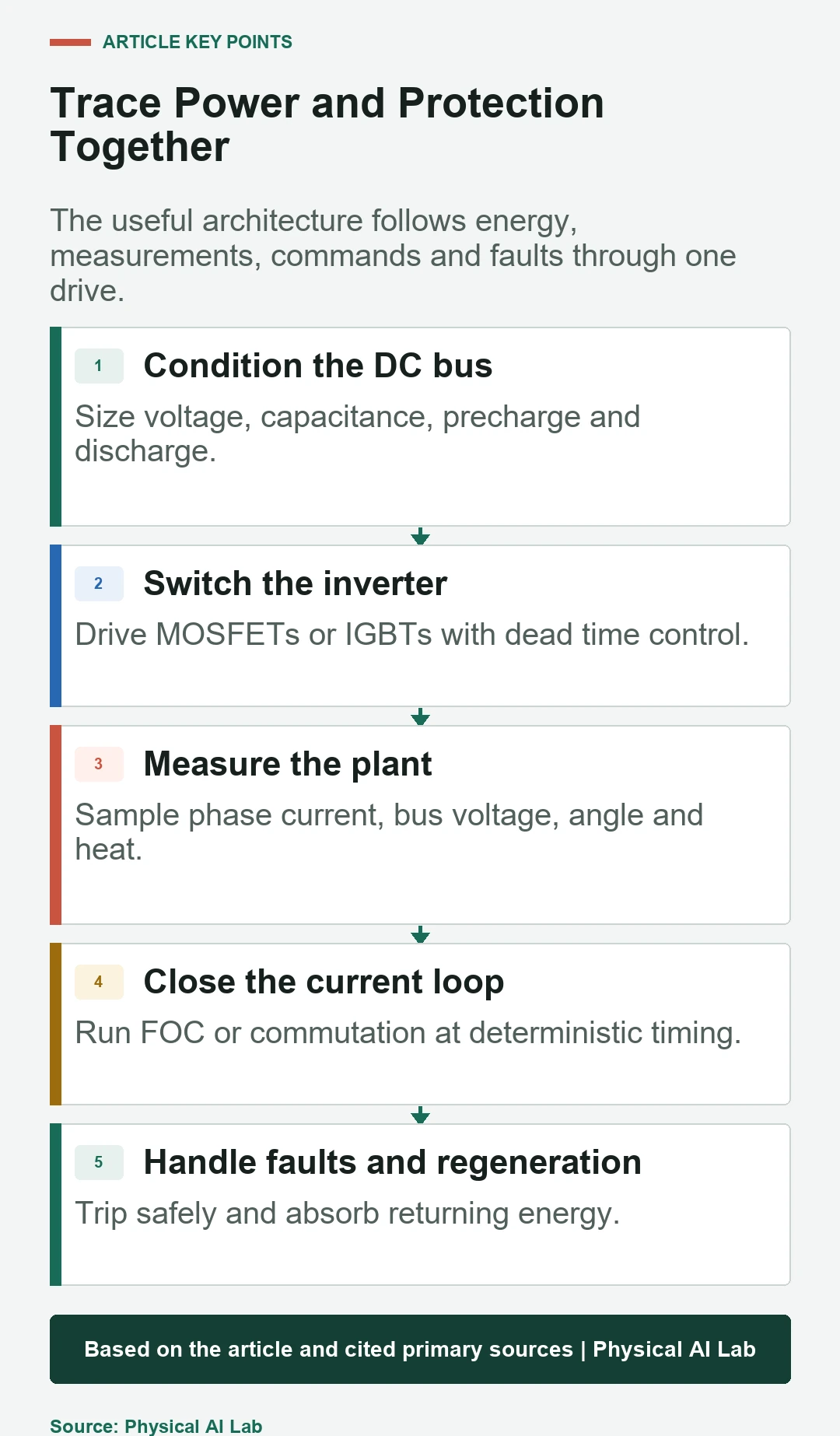
A robot motor driver converts DC-bus energy into controlled three-phase motor current while measuring the plant and reacting to faults. Its main blocks include bus conditioning, power inverter, gate driver, current and voltage sensing, control processor, rotor feedback, communication, thermal design and protection.
The driver is both a power converter and the fastest controller in the joint. Peak current alone does not define capability. Voltage margin, switching losses, current-sensor quality, firmware timing, regenerative-energy path and cooling determine the usable torque-speed and duty envelope.
Use this guide with the FOC guide and joint actuator tests. High-energy drive design and functional safety require qualified electrical design, current device data and application-specific validation.
The DC bus supplies and receives actuator energy
A battery, power supply or rectifier feeds the DC link. Input protection, contactor, fuse, reverse-polarity protection, precharge and bus capacitors manage connection and transients. The bus must supply acceleration current and may receive energy during deceleration.
Specify nominal, minimum and maximum voltage, source impedance and allowable ripple. Long cables and distributed joints create inductance and local transients. Measure at the drive terminals rather than assuming the central supply voltage.

The three-phase inverter switches the motor windings
Six transistor switches commonly form three half bridges. MOSFETs are typical at lower bus voltages; device choice depends on voltage, current, switching frequency, losses and safe operating area. Parasitic inductance and layout determine overshoot and electromagnetic noise.
Continuous phase current, peak phase current and DC-bus current are different quantities. State waveform, cooling, ambient and duration. Transistor, connector, copper and shunt temperatures can set different limits.
| Block | Primary function | Key measurement | Common failure |
|---|---|---|---|
| DC link | Store and distribute energy | Bus voltage and ripple | Overvoltage or inrush |
| Inverter | Switch three phases | Phase current and switch node | Shoot-through or overheating |
| Gate driver | Charge gates and enforce timing | Gate voltage and fault state | False turn-on |
| Control MCU | Run FOC and state machine | Loop timing and saturation | Jitter or software fault |
| Protection | Bound unsafe electrical states | Trip threshold and response | Failure to isolate |
Gate drivers control switching and dead time
The gate driver translates logic commands into rapid gate charge and discharge, provides high-side drive and may monitor desaturation or drain-source behavior. Dead time prevents both transistors in one leg from conducting simultaneously.
Too little dead time risks shoot-through; too much distorts applied voltage and current, especially near zero crossing. Verify gate waveforms with suitable isolated probes and the final layout. Firmware values do not show ringing or Miller-induced turn-on.
Current sensing sets torque-control quality
Low-side, phase or inline shunts and magnetic sensors offer different visibility, common-mode stress and sampling constraints. Amplifier bandwidth, offset, gain, saturation and ADC timing determine the current loop’s real feedback.
Calibrate each channel and monitor plausibility. Place sampling in valid PWM windows. Hardware overcurrent comparators should react faster than a software loop when destructive current can rise within switching cycles.
The control processor closes FOC at deterministic timing
The processor samples current and angle, runs transforms and PI loops, computes modulation and updates PWM. Motor-control interrupts must meet worst-case deadlines. Communication, logging and high-level tasks should not add uncontrolled jitter.
Use watchdogs, deadline monitoring and bounded state transitions. Record loop period, execution time and missed updates. A powerful processor does not compensate for poor interrupt architecture or noisy measurement.
Integrated and centralized drives trade wiring for environment
A joint-integrated drive shortens phase wires and can reduce central harness mass, but it lives near motor heat, vibration and limited volume. A centralized drive eases cooling and service but needs longer phase and sensor wiring and may increase electromagnetic interference.
Compare total harness, cooling, enclosure, connectors, service and communication latency. Distributed drives need robust time synchronization and fault containment. Central drives need careful cable shielding and reflected-wave or inductive-transient analysis where relevant.
| Architecture | Advantage | Constraint | Verification |
|---|---|---|---|
| Joint integrated | Short motor wiring | Heat and volume | Thermal-vibration test |
| Link distributed | Shared local power and network | Fault containment | Multi-axis load test |
| Central cabinet | Cooling and service access | Harness mass and EMI | Cable and transient test |
| Battery-local bus | Direct energy source | Voltage variation | Full state-of-charge range |
| Regenerative shared bus | Energy reuse among axes | Bus coordination | Worst simultaneous braking |
Protection needs both hardware and firmware layers
Overcurrent, short circuit, undervoltage, overvoltage, overtemperature, encoder fault and overspeed require defined responses. Hardware comparators can disable gates rapidly; firmware can manage controlled ramp-down, reporting and restart policy.
Choose thresholds from device limits and system hazards with measurement tolerance. Test faults at relevant current and speed using safe methods. A latched hardware trip and a communication error are different states and should not share an ambiguous reset.
Regenerative energy must have a destination
During deceleration or externally driven motion, the motor can act as a generator and return energy to the DC bus. A battery may absorb some energy, while a laboratory supply may not. Bus voltage can rise quickly if no sink exists.
Use a suitable battery path, shared-bus consumption, braking resistor, active front end or other designed sink. Coordinate overvoltage thresholds and mechanical stop strategy. Do not assume motor braking dissipates energy inside the motor.
Communication loss must lead to a defined local state
The drive should detect stale commands and distinguish normal hold, controlled stop, torque removal and brake coordination. The correct reaction depends on robot state and hazard. A network timeout should not leave the last current command indefinitely active.
Keep essential current limiting and electrical protection local. Validate packet loss, corrupted frames, time-sync loss and controller reset. Define what state survives a processor reboot and what authorization is required to re-enable torque.
A load bench should exercise control and protection
A useful bench combines motor, drive, controllable load, torque and speed measurement, bus instrumentation and temperature sensing. The ODrive documentation is one example of a motor-control platform reference, but every board and firmware revision needs its own limits and tests.
Map current tracking, torque-speed output, efficiency, regenerative voltage, thermal derating and fault response. Test both motor directions and electrical corner cases. Store hardware, firmware and configuration with the results.
- Define DC-bus source and regenerative sink.
- Validate gate timing and current sensing on hardware.
- Keep destructive-fault protection local and fast.
- Separate communication timeouts from safety functions.
- Test torque-speed, thermal and fault behavior together.
Frequently asked questions
Are a motor driver and motor controller the same thing?
The terms overlap; a driver emphasizes power conversion, while a controller may include the algorithms and higher-level state machine. State the included functions.
Does higher peak current always mean higher usable torque?
No. Motor constant, bus voltage, current waveform, duration, temperature and output transmission determine usable torque.
Should every robot joint contain its own drive?
Not always. Integrated and centralized architectures trade harness, heat, volume, service, EMI and fault containment.
Where does regenerative braking energy go?
It returns to the DC bus and must be absorbed by a battery, another load, braking resistor, active supply or other designed path.
What should happen when communication is lost?
The local drive should detect stale commands and enter a predefined bounded state coordinated with the robot’s stop and brake design.
Power Electronics Boundary Note
Motor drivers handle hazardous current, voltage and stored energy. Use current component limits and qualified power-electronics design, provide a regenerative-energy path, and validate hardware trips, thermal derating, communication faults and restart behavior.