Simultaneous localization and mapping estimates a robot trajectory while building or updating a representation of its environment. The two estimates depend on each other: motion is needed to place observations in the map, and a map is needed to correct accumulated motion error. SLAM is therefore an estimation problem, not simply a way to draw an occupancy image.
LiDAR, visual and visual-inertial SLAM differ in what they observe and how they fail. Range scans emphasize geometry, cameras use image appearance and projection, and visual-inertial systems combine image constraints with high-rate inertial propagation. Wheel odometry, depth, GNSS or other priors may supplement any of them.
Use this guide with the robot sensor-fusion guide and robot sensor overview. Choose a system from calibrated trajectory and downstream-task evidence, not from one attractive map screenshot.
SLAM estimates pose and map together
A robot begins with uncertain pose and receives observations from unknown or partly known landmarks, surfaces or image features. Relative motion links successive states, while repeated observations link the trajectory back to earlier places. Optimization or filtering finds a set of states and map variables that best agrees with these constraints.
Gauge freedoms and reference frames must be defined. A local map can be internally consistent without a globally surveyed origin. Scale is observable in metric range systems but not always from a single camera without additional information. State which outputs are metric, gravity aligned and globally referenced.

The front end converts sensor data into constraints
A SLAM front end detects image features, aligns scans, estimates visual odometry or otherwise associates new observations with earlier state. It supplies relative-pose or landmark constraints and uncertainty. Bad association creates a confident wrong edge that a back end may not be able to repair.
Timestamp and extrinsic calibration affect every constraint. Rolling shutter, motion distortion, wheel slip and IMU bias need suitable models or preprocessing. Monitor matching score, inlier count and residual distribution rather than assuming every accepted match is equally reliable.
| SLAM layer | Primary job | Evidence | Failure |
|---|---|---|---|
| Sensor preparation | Time and calibrate inputs | Timestamp and calibration residual | Motion distortion |
| Front end | Create local constraints | Inliers and match residual | Wrong association |
| Odometry | Propagate local motion | Increment and covariance | Accumulated drift |
| Loop closure | Recognize a revisit | Geometric verification | False or missed loop |
| Back end | Optimize graph or state | Objective and residual | Inconsistent solution |
The back end distributes accumulated error
A pose graph represents robot poses as nodes and relative constraints as edges. When a valid loop closure links the current pose to a previously visited place, graph optimization can redistribute drift across many poses instead of applying one abrupt local patch.
The current slam_toolbox documentation describes pose-graph mapping and localization workflows. Save the serialized graph and configuration when repeatability matters; a rendered image alone loses constraint and uncertainty information needed for later diagnosis.
LiDAR SLAM observes geometric range structure
Two-dimensional LiDAR SLAM aligns planar scans and works well when walls and objects create distinctive geometry near the scan plane. Three-dimensional systems add vertical structure and support richer motion, but increase data, computation and calibration burden.
Google’s archived Cartographer repository illustrates local trajectory building and global pose-graph ideas. Range sensing is not immune to failure: long featureless corridors, symmetry, glass, mirrors, dust, rain and moving crowds can produce missing or misleading returns.
Visual SLAM uses appearance and camera geometry
Monocular visual SLAM tracks image features or direct intensity relationships and can create sparse or dense maps depending on the system. Stereo or RGB-D cameras add metric depth within their reliable range. Cameras provide rich appearance but depend on exposure, focus, texture and visibility.
Motion blur, repeated patterns, darkness, glare and large illumination change reduce association quality. Dynamic people or screens can move features that the system assumes are static. Camera calibration, shutter model and exposure strategy are part of the estimator, not separate cosmetic settings.
Visual-inertial SLAM adds high-rate motion evidence
ORB-SLAM3 is an open reference covering visual, visual-inertial and multi-map research workflows. Its repository documentation also shows that camera-IMU calibration and initialization are explicit requirements, not optional improvements.
An IMU helps bridge rapid motion and low-texture intervals and makes gravity and metric scale observable under suitable excitation. Bias, timing and axis errors integrate rapidly, however. Weak initialization or unexciting motion can leave scale, bias or orientation poorly observed even when the track looks smooth.
| Family | Strong observation | Typical weakness | Validation scene |
|---|---|---|---|
| 2D LiDAR | Planar geometry | Glass and repeated corridors | Mixed wall geometry |
| 3D LiDAR | Metric 3D structure | Cost and motion distortion | Multi-level route |
| Monocular visual | Appearance and bearing | Scale and lighting | Texture and exposure sweep |
| Stereo or RGB-D | Metric visual depth | Range and optical failure | Near-far objects |
| Visual-inertial | Fast motion and gravity | Timing, bias and initialization | Exciting six-axis motion |
Loop closure needs geometric verification
Place recognition proposes that two observations came from the same location. A separate geometric check should verify the relative transformation before adding a loop. Repeated shelves, doors or corridors can produce perceptually similar but physically different places.
Test both false-positive and missed-loop behavior. One false high-confidence closure can warp an otherwise useful map, while no closures allow drift to remain. Record proposals, verification residuals, accepted edges and the trajectory change caused by each loop.
Trajectory metrics reveal what the map image hides
Absolute trajectory error measures alignment to a reference over the route, while relative pose error examines local drift over selected intervals. Also measure loop consistency, relocalization time, tracking-loss rate, map repeatability and CPU or memory behavior over long sessions.
Report alignment method and reference uncertainty. A fitted transform can hide scale or global offset, so retain raw and aligned metrics. For navigation, add localization jump, path-clearance error and repeated-route success. A geometrically crisp wall map can coexist with biased robot pose.
Failure tests should reproduce the real environment
Build routes with straight corridors, rotations, elevators or ramps, glass, changing lights, dynamic objects and temporary occlusion as relevant. Vary speed, acceleration and sensor temperature. Test startup at several map locations rather than always from one known origin.
Remove wheel odometry, cover a camera, block part of a scan or introduce timestamp delay. Verify uncertainty, tracking-loss detection and recovery. A robust system must know when confidence is weak; continuing with a precise-looking wrong pose can be worse than stopping.
SLAM, localization and navigation have different roles
SLAM estimates a trajectory and map, localization estimates pose in an existing representation, and navigation selects and controls motion toward a goal. One package can expose several modes, but the claims remain separate. Map maintenance and localization-only operation also have different data-retention and change policies.
Define frame continuity for controllers during global correction. Keep local odometry smooth while applying map-level corrections through a separate transform where appropriate. Validate the map with the planner footprint, obstacle layers and repeat routes so estimation output is proven useful downstream.
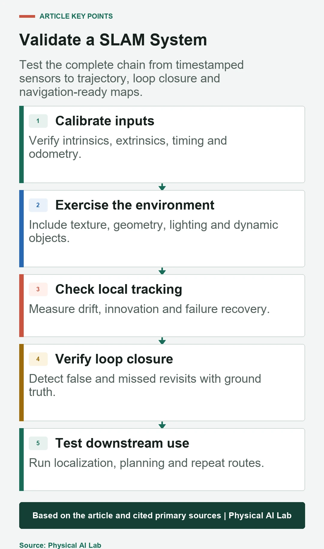
- Calibrate timing, intrinsics and sensor extrinsics.
- Measure local drift and global loop consistency.
- Geometrically verify loop closures.
- Test lighting, geometry, motion and dynamic-object failures.
- Validate localization and navigation on saved maps.
Frequently asked questions
Are SLAM and navigation the same technology?
No. SLAM estimates pose and map; navigation uses a world representation and state estimate to plan and control motion.
Is LiDAR SLAM always more accurate than visual SLAM?
No. Accuracy depends on environment, motion, calibration, algorithm and reference. Geometry-poor or reflective scenes can defeat LiDAR just as lighting can defeat vision.
Is loop closure mandatory?
Not for every short task, but without global references or revisits, local drift generally accumulates over longer routes.
Can SLAM work without wheel encoders?
Yes. LiDAR, visual-inertial or other methods can estimate motion, but encoder input can add useful complementary evidence when modeled correctly.
Does a clean-looking map prove accurate localization?
No. Evaluate trajectory error, loop consistency, repeated localization and downstream navigation, not only the rendered map.
SLAM Evidence Boundary Note
SLAM output depends on calibration, environment, motion, association and estimator configuration. Validate trajectories and failure recovery with an independent reference and the downstream navigation stack before deployment.