EtherCAT and CAN FD can both carry cyclic robot-joint commands and state, but they organize communication differently. EtherCAT sends Ethernet frames through a sequence of devices that read or write process data while the frame passes. CAN FD uses a shared priority-arbitrated bus with a flexible data phase and larger payload than classic CAN.
Nominal link rate does not decide the robot. Axis count, cyclic bytes, synchronization, message priority, diagnostic traffic, cable length, topology, electromagnetic environment, error handling and safe reaction determine whether deadlines are met. The design must be sized from worst-case traffic and measured on final hardware.
Use this guide with the robot joint-control guide and motor-driver architecture. A fast network is an enabling layer, not proof of control stability or functional safety.
EtherCAT processes one frame across many devices
The EtherCAT Technology Group’s technology overview describes on-the-fly processing: SubDevices extract or insert assigned process data as an Ethernet frame passes. This can move many axes’ cyclic data in a compact frame rather than sending a separate transaction to each joint.
Topology can follow line, tree or other supported arrangements, but physical ports and device behavior determine the actual path. Frame return, cable breaks and redundancy options need explicit design. Ethernet connectors and 100 Mbit/s signaling do not make ordinary switched Ethernet behavior equivalent to EtherCAT.
CAN FD shares a bus through identifier arbitration
CiA’s CAN FD introduction explains that arbitration begins under CAN rules and the data phase can use a higher bit rate when configured. Frames can carry up to 64 data bytes, reducing overhead for some payloads compared with classic CAN.
All nodes observe the shared bus, and identifiers encode arbitration priority. A lower-priority frame can wait when higher-priority traffic is present. Timing therefore depends on the complete message set, bit stuffing, retransmission and error state, not only the configured data-phase rate.
| Property | EtherCAT | CAN FD | Robot question |
|---|---|---|---|
| Medium access | MainDevice cyclic frames | Priority arbitration | Who controls worst case? |
| Data organization | Process image in passing frame | Individual identified frames | How many messages? |
| Synchronization | Distributed Clocks available | Application or hardware method | How aligned are samples? |
| Topology | Line and flexible variants | Terminated shared bus | What wiring fits the body? |
| Fault evidence | Working counters and diagnostics | Error counters and bus states | How is degradation handled? |
Distributed Clocks align events across EtherCAT nodes
EtherCAT Distributed Clocks synchronize local device clocks and compensate propagation delay. Inputs can be sampled and outputs triggered from local synchronized time rather than the uncertain instant a frame arrives. This matters when joint velocity is derived from equidistant position samples.
The technology overview states sub-microsecond synchronization under its documented mechanism, but an integrated robot must still verify its controller, hardware interface and devices. A synchronized device clock does not by itself bound application computation or actuator response.
CAN FD timing comes from a schedulable message set
Assign identifiers from deadline and criticality rather than convenience. Calculate each frame’s worst transmission time, blocking by one lower-priority frame where applicable, interference from higher-priority messages and retransmission assumptions. Keep utilization margin for diagnostics and fault recovery.
Separate fast torque or state messages from slower temperature, configuration and logs. Pack related signals only when their update and failure semantics match. One oversized message can delay a short urgent message if its identifier or start time is poorly chosen.
Bus load starts with axis data and update rate
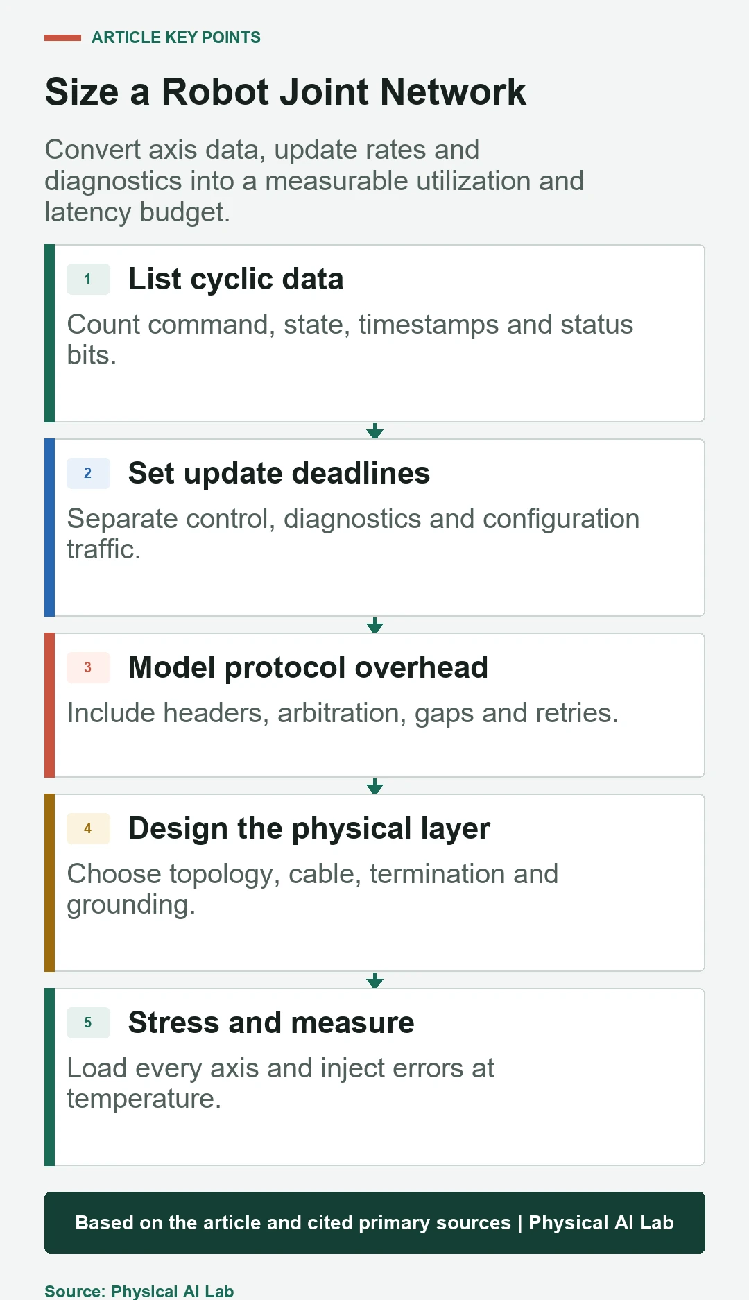
List commanded position, velocity, torque or current; measured state; timestamps; status; fault flags and sequence counters. Multiply payload and protocol overhead by axis count and frequency. Add acyclic configuration, firmware, diagnostic and synchronization traffic.
Use physical-layer bit time for CAN FD and actual EtherCAT frame composition for EtherCAT. Include startup and fault bursts, not only nominal steady state. Retain a margin for future signals and device variability rather than designing to one spreadsheet value at 99 percent utilization.
Wiring and electromagnetic compatibility can decide the choice
CAN FD needs the specified bus topology, termination and stub discipline for the chosen bit timing. EtherCAT device-to-device links need appropriate industrial cable, connectors, grounding and port design. Robot joints add repeated flexing, compact routing and motor-switching noise.
Inspect differential signals, common-mode stress, connector retention and shield bonding on the assembled robot. Test minimum and maximum cable configurations, moving harnesses, hot drives and regenerative events. A network can pass on a bench yet fail near an inverter or after cable wear.
| Test | Stimulus | Record | Failure criterion |
|---|---|---|---|
| Full cyclic load | All axes and diagnostics | Latency and jitter tails | Deadline miss |
| EMC stress | Motor switching and regeneration | Errors and retries | State transition |
| Cable motion | Bend and torsion cycles | Link interruptions | Intermittent fault |
| Node fault | Reset or disconnect | Fault containment | Unsafe stale command |
| Clock test | Long hot run | Offset and drift | Sample misalignment |
Drive profiles sit above the physical network
CiA 402 defines a drive and motion-control device profile for CANopen. The CiA overview also helps explain why CANopen over CAN and CAN application protocol over EtherCAT are distinct layers. Do not equate a profile with the underlying bus.
State machines, modes, units and fault codes must be versioned for every drive. Similar object names do not guarantee identical transition or scaling behavior. Validate enable, quick stop, fault reset and command timeout against the actual device manual.
Average latency hides arbitration and fault tails
Record cycle time, send-to-apply latency, sample-to-controller data age, synchronization offset, jitter percentiles and maximums. Align clocks or use physical triggers so software timestamps can be trusted. A low mean with rare multi-cycle delay can destabilize a tight joint loop.
Inject competing traffic, error frames, node resets and cable disturbances. Test at temperature and maximum axis count. Keep packet or frame traces with controller logs so a mechanical vibration can be separated from a delayed command or stale sensor sample.
Safety communication requires a validated safety layer
EtherCAT or CAN FD transport speed does not automatically provide a safety function. Safety protocols, certified devices, diagnostics, timing assumptions, safe states and system-level validation are separate requirements. A standard error counter is not a substitute for required risk reduction.
Define what each joint does when commands are stale, synchronization is lost or the bus enters an error state. Keep fast electrical protection local to the drive. Coordinate stop behavior across axes so a network fault does not create uncontrolled gravity or contact motion.
Select the network from the robot architecture
EtherCAT is attractive for many tightly synchronized axes and a centralized cyclic process image. CAN FD can fit compact distributed joints, priority-based messages and modest payloads with simpler shared wiring. Hybrid robots may use one network inside an actuator group and another for higher-level communication.
Prototype the hardest configuration: maximum nodes, longest harness, full data set, hottest drives and injected faults. Compare cost, connector mass, software, diagnostics, service and certification needs. Choose measured margin and recoverability rather than one protocol slogan.
- Build a complete cyclic and acyclic signal dictionary.
- Calculate worst-case frame or message timing.
- Measure sample age and command-apply latency.
- Stress final cables beside active motor drives.
- Define stale-command and network-fault reactions locally.
Frequently asked questions
Is EtherCAT always faster than CAN FD?
Not as a universal statement. EtherCAT offers high-throughput cyclic processing and distributed clocks, while actual deadlines depend on topology, devices and implementation.
Can CAN FD control a humanoid's joints?
It can support joint networks when message timing, utilization, synchronization and fault requirements fit. The complete message set must be analyzed and tested.
Are EtherCAT and CANopen competing layers?
EtherCAT is a network technology; CANopen is an application framework commonly used over CAN and profiles can also be transported over EtherCAT through CoE.
Does a faster network automatically improve control?
No. Sensor timing, computation, actuator dynamics, loop design and jitter must all support the higher rate.
Does a ring or redundant path make cable faults safe?
It may improve availability, but safety requires defined detection, state transition and validated risk reduction for the complete system.
Robot Network Boundary Note
Protocol capabilities vary by controller, device, cabling and configuration. Verify current specifications and measure worst-case timing, synchronization, electromagnetic faults and stop behavior on the final robot.