Nav2 costmaps combine several claims about where a mobile robot may travel. The static layer contributes mapped occupancy, observation layers add and clear live obstacles, inflation turns geometry into graded clearance cost, and filters apply policies such as keepout or speed restrictions. The final grid is a contract consumed by planners and controllers.
A configuration can look convincing in RViz while carrying stale observations, an incorrect footprint or a frame mismatch. Tune a layer only after its source, timestamp, transform, update behavior and failure response are observable. Otherwise a parameter change may hide the symptom rather than correct the environment model.
Use this guide with the robot SLAM guide and TF2 frame guide. Validate the robot on representative floor, obstacle and traffic conditions before production release.
Treat the costmap as a layered environmental contract
The costmap is not a raw sensor image. Each plugin transforms a particular source into cell costs under declared frames, dimensions, combination rules and timing. Record which layer owns mapped walls, transient obstacles, clearance, restricted zones and unknown space so two layers do not silently contradict each other.
The current Nav2 Costmap 2D documentation describes plugins and filters separately. Keep that distinction in configuration reviews: ordinary plugins contribute to the combined costmap, while filters are applied after the layered map for policy effects such as keepout or speed limits.

Choose global and local map responsibilities
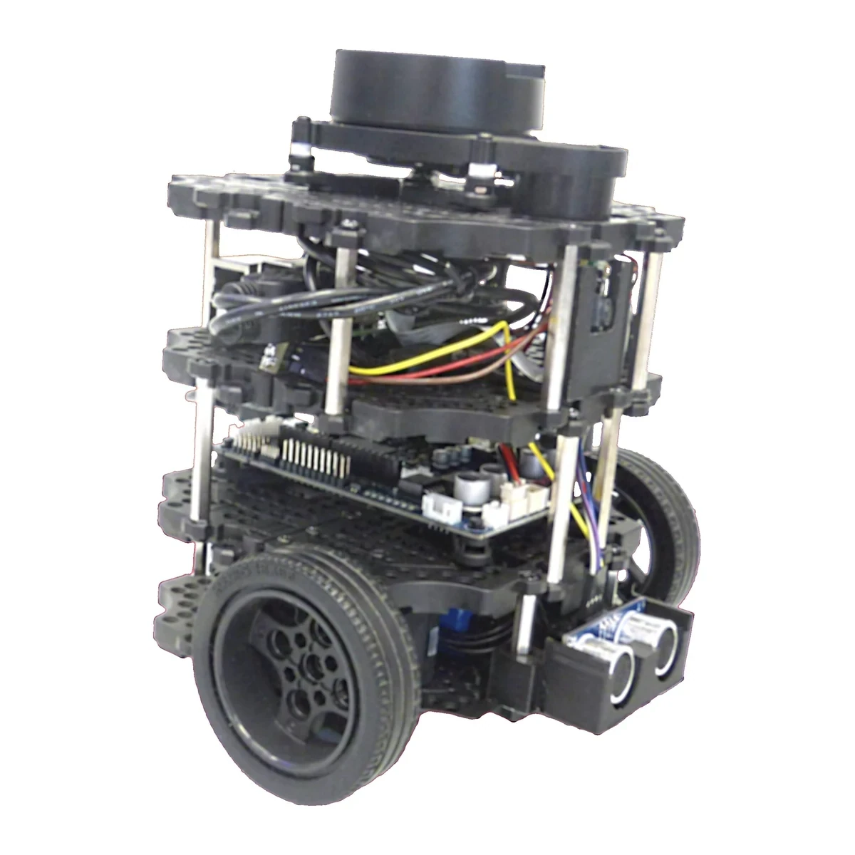
A global costmap usually represents the route-scale environment in a stable global frame, while a local rolling costmap supplies current nearby constraints for control. They may use different dimensions, update rates and observation sources. Copying one configuration into both maps wastes resources and confuses fault ownership.
For each map, state its planning consumer, frame, rolling-window behavior, resolution and maximum acceptable age. A global planner may tolerate a slower map update than a local controller, but neither should consume a grid whose transform or source freshness exceeds the navigation contract.
| Layer or setting | Primary job | Failure symptom | First evidence |
|---|---|---|---|
| Static layer | Mapped occupancy | Route crosses wall or blocks opening | Map version and frame |
| Obstacle layer | 2D marking and clearing | Transient object missing or persistent ghost | Scan age and raytrace |
| Voxel layer | 3D observation buffering | Height obstacle mishandled | Point cloud and voxel settings |
| Inflation layer | Clearance cost | Corner cutting or needless detour | Footprint and cost gradient |
| Keepout filter | Policy restriction | Robot enters prohibited zone | Mask alignment and filter info |
Freeze robot geometry before tuning clearance
Use a polygon footprint when the base is not well represented by a circle. Include fixed protrusions that can collide, and define how attachments or carried loads update the footprint. Padding is an additional margin; it should not compensate for an incorrect physical outline or localization uncertainty that varies with conditions.
Verify geometry by placing known points around the stationary robot and checking collision classification at several headings. Rotating an asymmetric footprint can expose errors hidden on straight paths. Version the footprint with the mechanical configuration and reject an unknown payload shape instead of assuming the smallest base.
Configure the static layer as versioned map evidence
The static layer commonly subscribes to an occupancy grid and transfers mapped structure into the costmap. Confirm map topic, frame, durability behavior and whether updates are expected. A robot that starts before receiving the intended map can appear ready with an empty or old environmental model.
Store map identity and checksum in deployment records. Test replacement, restart and map-server loss. Decide whether the robot stops, continues for a bounded interval or degrades to another mode when static evidence disappears; the correct choice depends on the local map and operational risk.
Make obstacle marking and clearing independently observable
Observation layers usually mark cells from detections and clear along sensor rays. A source can mark correctly while clearing fails because raytrace range, minimum range, transform timing or invalid returns differ. Inspect both operations with a temporary obstacle that enters and leaves each part of the sensor field.
Set obstacle and raytrace ranges from verified sensor performance, not maximum brochure distance. Record source type, topic, frame, persistence and expected rate. When a source stops, measure how long its obstacle evidence remains and whether that duration matches the stopping-distance assumption.
| Test | Controlled change | Expected map response | Reject when |
|---|---|---|---|
| Marking | Insert target | Cells become occupied within limit | Target omitted or delayed |
| Clearing | Remove target | Ray returns cells to allowed state | Ghost persists beyond limit |
| Source loss | Stop messages | Declared stale-data policy occurs | Old grid looks current |
| Transform delay | Delay TF | Update is rejected or bounded | Misplaced obstacle accepted |
| Restart | Restart sensor and costmap | Layer recovers without duplicate state | Unknown gap is hidden |
Use voxel data only when height changes the decision
A voxel layer can buffer three-dimensional observations before projecting collision information into two dimensions. It is useful when obstacle height and overhang behavior matter, but its vertical origin, resolution, voxel count and marking thresholds create another model that must be tested against the robot body.
Choose minimum and maximum obstacle heights from collision geometry and sensor placement. Test low pallets, table edges, forks and overhangs. A 3D point cloud does not guarantee a correct obstacle decision when ground removal, sparse returns or projection thresholds discard the relevant structure.
Tune inflation from footprint clearance and behavior
Inflation assigns higher cost near lethal obstacles so planners and controllers can prefer clearance. Inflation radius defines the affected neighborhood, while the scaling factor shapes how quickly cost decays. These parameters influence preference; they do not replace exact footprint collision checking.
Start from required physical clearance and localization uncertainty, then test corridors, doorways and corners. Measure contact-free pass rate, path length and false blockage. If the robot oscillates near a narrow opening, inspect geometry, localization and controller behavior before simply shrinking inflation.
Apply keepout and speed policy with aligned masks
Costmap filters can express policy overlays such as keepout or speed zones. Their masks and metadata must align with the intended map frame, origin and resolution. A visually shifted mask can create a dangerous policy gap even when the filter plugin is active and reporting no error.
Test both sides of every boundary and after map reload. Record who owns policy changes and how quickly robots receive them. Treat a missing or stale mandatory filter as a readiness failure, not as permission to use the unfiltered costmap.
Budget update, publish and transform timing separately
Update frequency controls how often the map processes inputs; publish frequency controls how often a representation is sent for consumers or visualization. Sensor rate, transform availability and executor delay also affect cell age. Increasing publish frequency cannot make stale source evidence fresh.
Timestamp observations and measure arrival-to-map latency under CPU and network load. Track worst-case and high-percentile age, not only average rate. Define a timeout response for every required source so the controller does not continue because the last displayed grid still looks plausible.
Separate unknown space from confirmed free space
Unknown means the system lacks evidence, not that the area is occupied or free. The choice to track unknown space and whether planners may traverse it should follow mission context. Exploration, a mapped warehouse and a public corridor can require different policies.
Exercise map boundaries, sensor shadows and newly opened areas. Report unknown-cell behavior in logs and acceptance results. Converting unknown to free may improve reachability while eliminating the evidence needed to explain why the robot entered an unobserved region.
Diagnose layer ownership before parameter tuning
When navigation fails, save the individual layer outputs, combined costmap, transforms, footprint, sensor samples and planner request on a common timeline. A blocked route may come from a static wall, an uncleared observation, inflation or a keepout mask; the corrective action differs for each owner.
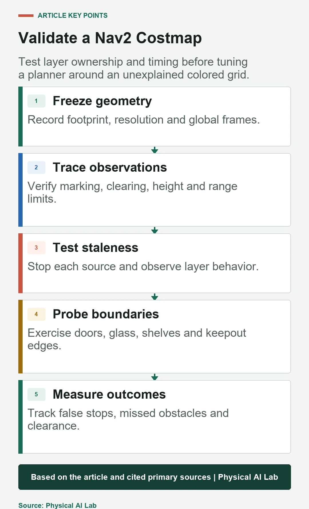
Change one hypothesis at a time and replay the same evidence where possible. Compare false-positive stops, missed obstacles, path clearance and recovery time. Avoid declaring success from a single visually improved run because environmental variance can conceal the original defect.
Release costmaps with a physical regression suite
Build trials for glass, dark material, thin legs, low objects, overhangs, doors, narrow aisles, moving people and source failure. Include robot rotations and carried loads. Verify both detection and clearing, plus the response when transforms or maps restart during motion.
Store software versions, plugin order, parameters, maps, sensor firmware and test distributions with results. Use this release checklist whenever geometry, sensing, localization or navigation plugins change.
- Name the source, frame and age limit for every layer.
- Verify marking and clearing as separate behaviors.
- Align policy masks and reject stale mandatory filters.
- Measure physical clearance with the deployed footprint.
- Keep individual-layer evidence for incident diagnosis.
Frequently asked questions
What are the default Nav2 costmap plugins?
Current Nav2 documentation lists static, obstacle and inflation layers as defaults when the plugin list is not overridden.
Should global and local costmaps use the same layers?
Not necessarily. Their consumers, frames, spatial extent, update rates and required evidence can differ.
Does inflation make a robot physically larger?
No. It changes cell cost around obstacles. The footprint and padding describe collision geometry and margin.
Why does an obstacle remain after it is removed?
Clearing may lack valid rays, range, transforms or timing. Inspect clearing independently from marking.
Is an RViz costmap enough for acceptance?
No. Acceptance needs timed physical tests, source-loss behavior and measured clearance under representative conditions.
Costmap Evidence and Safety Boundary
A costmap is an application environment model, not an independent safety-rated protective device. Validate sensing, timing and stopping safeguards for the robot and workplace risk.