TF2 answers a precise question: how can data expressed in one coordinate frame at a particular time be represented in another frame? Many apparent geometry bugs are actually disagreements about frame identity, transform direction, timestamp or which component owns an edge in the tree.
A mobile robot often separates a globally corrected map frame from a locally continuous odom frame, then connects base_link to sensors, manipulators and tools. A manipulator adds flange and tool-center-point frames. Each edge needs one responsible publisher and a defensible physical meaning.
Use this guide with the robot calibration guide and sensor-fusion guide. TF2 can apply a transform consistently, but it cannot prove that the calibration or source measurement is correct.
Name the frame, direction and time before the numbers
Write every observation as a quantity expressed in frame A at time t. Then state the desired output frame B. This sentence prevents a common mistake: treating a three-number position as meaningful without its coordinate basis or applying the inverse of the required transform.
Inspect the message header at the source. A visualization may silently transform data into its fixed frame and hide the original identity. Preserve source frame and timestamp through logs so a later investigation can distinguish a sensor error from a transform error.

A transform changes representation between frames
A rigid transform combines rotation and translation. The transform from parent to child describes the child’s pose relative to the parent under the TF2 convention, while a lookup request specifies target and source frames for transforming data. Casual language such as camera-to-base can be ambiguous about which operation is intended.
Check composition with a known point or axis, not only with quaternions printed in a terminal. Unit conventions, right-handed axes and rotation representation are summarized in REP 103. Normalize quaternions and avoid converting repeatedly through Euler angles.
If an imported mesh appears mirrored, separate the asset’s handedness from the frame’s rigid pose before changing a quaternion. Our mirrored robot mesh geometry study compares a reflected object transform with a reflected shape under a proper pose. It is an AI-operated Blender study, not a ROS/TF or hardware test.
| Frame | Typical meaning | Expected behavior | Common mistake |
|---|---|---|---|
| map | Globally corrected world reference | May jump after localization correction | Using it for local continuity |
| odom | Locally continuous motion reference | Drifts over long distance | Treating it as globally accurate |
| base_link | Robot body reference | Moves with the robot | Placing it inconsistently |
| sensor optical | Measurement-axis convention | Fixed to sensor mount | Confusing housing and optical axes |
| tool0 or TCP | Operational tool point | Moves with manipulator | Using flange as the task point |
Separate global accuracy from local continuity
The standard mobile-frame relationship commonly places map above odom and odom above base_link. Localization may update map-to-odom when global evidence arrives, while wheel, visual or inertial odometry supplies the continuous odom-to-base_link motion used for local control.
This split lets a global correction move the robot in map without inserting the same jump into the locally continuous odom trajectory. REP 105 defines the conventional meanings. A project can extend them, but every consumer must share the extension.
Keep TF as a tree with one owner per child
TF2 assumes a tree of coordinate frames. Each child has one parent at a time, producing a unique path between connected frames. Two nodes publishing the same child can make the transform alternate or appear plausible while representing two different estimates.
Create an ownership table that lists parent, child, publisher, static or dynamic status, update rate and source of truth. Namespaces help multi-robot systems, but a prefix does not resolve conflicting responsibility. Monitor for disconnected subtrees and unexpected publishers during startup.
Static and dynamic transforms have different owners
A static transform represents a relationship that should not change during operation, such as a rigid sensor mount or a calibrated tool attachment. Dynamic transforms represent joints, mobile motion or estimates that evolve. Publishing a changing relationship as static freezes an error into every downstream result.
A nominal CAD transform and a calibrated transform should not compete. Decide which is authoritative and version it with the hardware configuration. If a tool changer alters the relationship, publish the active tool frame according to lifecycle state rather than leaving several valid-looking TCPs ambiguous.
| Symptom | First check | Likely class | Independent test |
|---|---|---|---|
| Frame missing | Publisher and namespace | Lifecycle or discovery | Inspect active edges |
| Data rotated 90 degrees | Optical convention | Axis mismatch | Transform unit axes |
| Extrapolation error | Message and transform stamps | Clock or buffer | Compare time domains |
| Map jumps but odom is smooth | map-to-odom owner | Expected localization correction | Plot both trajectories |
| Tool misses consistently | TCP and kinematic calibration | Geometric bias | Measure independent targets |
Time is part of every dynamic transform
TF2 buffers transforms over time and interpolates when possible. A request outside the buffer produces extrapolation errors. Asking for the latest transform can make an operation run but combine measurements from different physical moments, especially on moving robots.
Compare sensor hardware time, driver stamp, host clock and transform publication time. Synchronize computers and define how clock reset or simulation time is handled. The maximum acceptable transform age should come from motion speed and spatial-error tolerance, not from a convenient timeout.
Optical frames do not follow body-frame axes
Camera optical frames conventionally use different axis directions from many robot body frames. A camera housing can also expose color, left imager, right imager, depth and aligned-output frames. Similar names do not imply identical origins or axes.
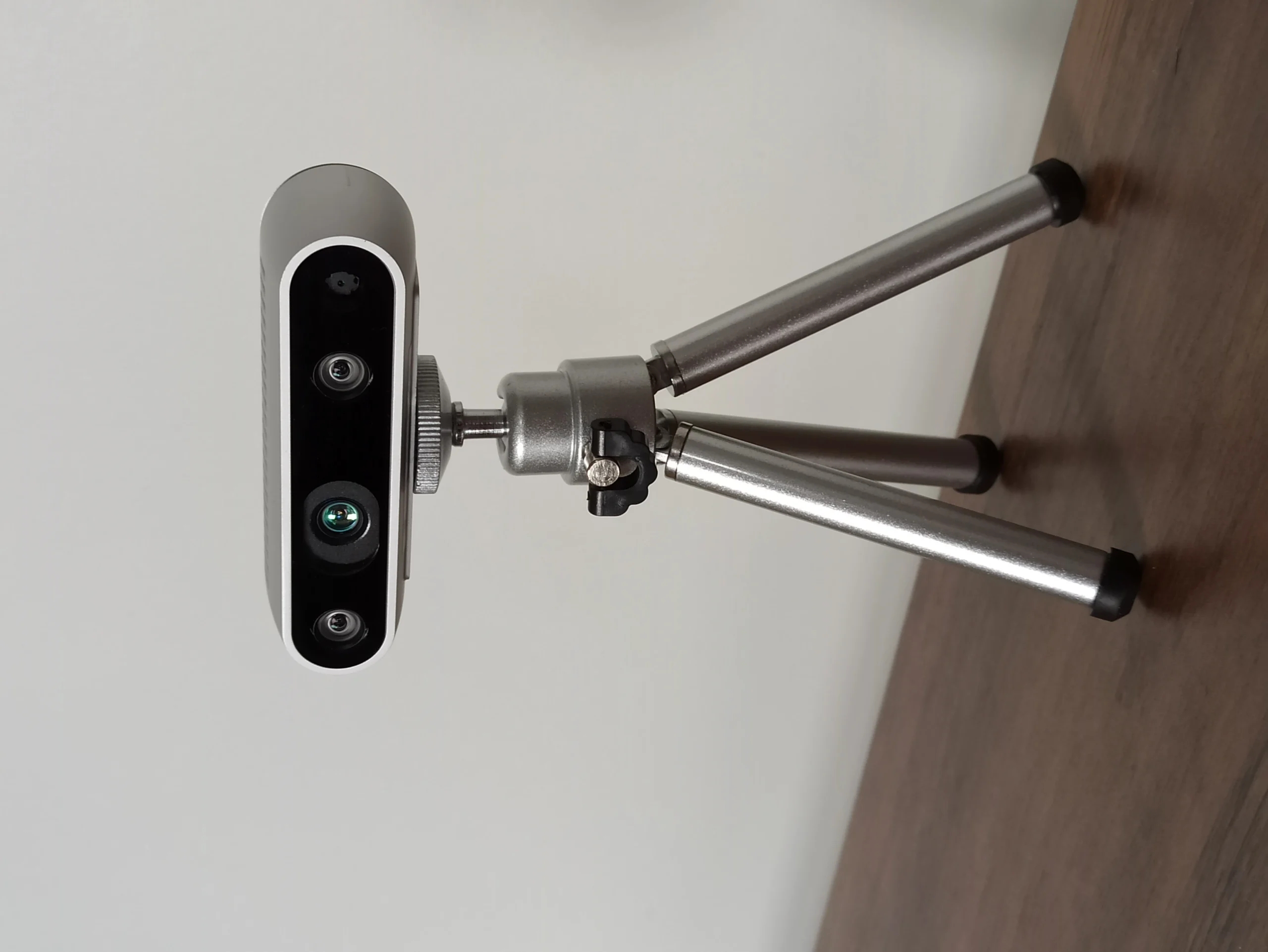
Read the driver’s frame definitions and inspect transformed basis vectors. If an image looks correct while a point cloud is sideways, check optical-frame convention and the message frame_id before changing calibration. The physical photograph of a camera cannot reveal the exact software frame tree.
The tool frame should represent the real task point
A robot flange frame describes the mechanical interface; a tool-center-point frame describes the point and orientation used for the task. Grasp approach, welding direction and force-control axes may each need an explicit frame linked to the active tool.
Calibrate the TCP using multiple poses and validate on independent targets. A transform can be syntactically correct yet carry a biased tool length. Keep tool identity, calibration result and mounting verification together so changing a gripper does not retain the old task frame.
Debug existence, path, direction, time and value
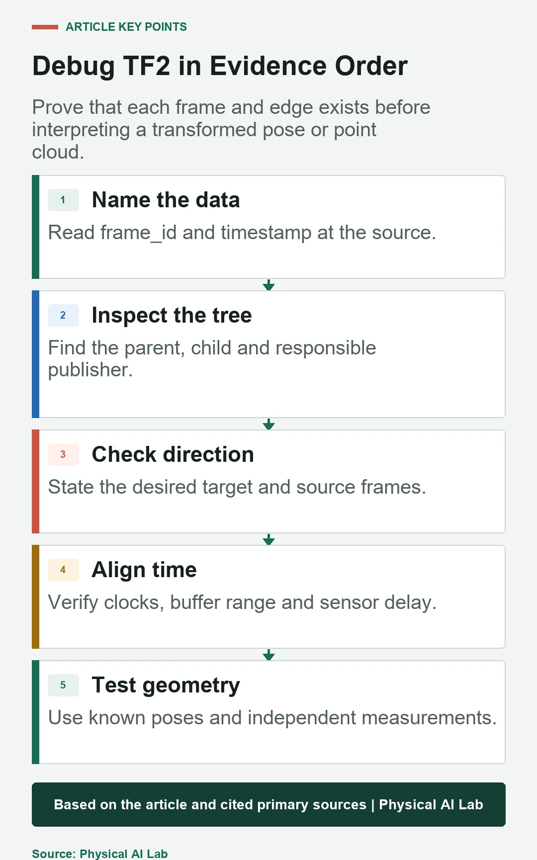
Start by confirming that source and target frames exist and have one connected path. Next inspect the path and publishers, state the intended lookup direction, verify time availability and only then evaluate numeric values. This order avoids adjusting a calibration to compensate for a naming or timestamp mistake.
Use TF2 inspection tools, tree diagrams and echo commands from the deployed ROS branch. The Jazzy TF2 API documentation confirms the tree and coordinate-convention assumptions. Save a short transform trace with the failing sensor message.
Multi-robot systems need explicit global authority
Give each robot unique base, sensor and tool frames. Decide whether the fleet shares one map, maintains per-robot maps or uses a site frame that connects them. A transform between maps implies a registration estimate with uncertainty and an owner; it is not merely a naming convenience.
Handle robot restart and re-localization without leaving stale global edges. When data crosses robots, preserve its original frame, timestamp and map version. Network delay and clock offset can otherwise look like a spatial disagreement between agents.
Validate geometry with independent physical evidence
Test static transforms with measured offsets, known targets and several orientations. Test dynamic transforms during controlled motion and after restart. For localization, compare trajectories in both map and odom. For tools and cameras, reserve validation poses that were not used during calibration.
Separate repeatability from absolute accuracy and record uncertainty. A clean TF tree proves connectivity, not correctness. The robot latency guide is useful when moving-scene error may come from delayed perception rather than the spatial calibration itself.
Operate TF2 as a versioned interface contract
Document frame names, meanings, axis conventions, parent-child ownership, update rates, clock source and calibration version. Add automated checks for duplicate children, missing required paths, stale transforms and implausible magnitudes during continuous integration and startup.
Use an acceptance checklist that ties graph structure to real geometry. That makes coordinate behavior reviewable across software, sensor and tool changes.
- Define source frame, target frame and timestamp.
- Assign one publisher to every child frame.
- Separate static calibration from dynamic estimation.
- Test optical and tool axes with known geometry.
- Version the tree with hardware and clock configuration.
Frequently asked questions
Why are both map and odom needed?
Map supplies global consistency while odom supplies local continuity. Localization corrections can change map-to-odom without forcing a jump in local odometry.
Will a larger TF2 buffer fix extrapolation errors?
Only if the requested timestamp should legitimately be retained. Clock disagreement, future stamps and excessive pipeline delay require separate correction.
Can every fixed relationship use static_transform_publisher?
Only relationships that remain fixed for the active configuration. Joints, changing tools and estimated motion need an appropriate dynamic owner.
Why is a point cloud rotated when the image looks correct?
The point cloud may use an optical frame with different axes, or its frame_id may not match the transform applied by the viewer.
Can a TF tree contain a loop for feedback correction?
No. TF2 expects a tree. Estimation feedback should update the value of an owned edge, such as map-to-odom, without creating a second parent path.
Coordinate Transform Evidence Boundary
TF2 provides transform storage and application. It does not establish calibration accuracy, clock validity or estimator correctness; validate those with independent physical and temporal evidence.