A 2D LiDAR produces ranges along one scan plane. A 3D LiDAR produces points across horizontal and vertical angles. The third dimension can reveal obstacle height, slopes and overhangs, but it also adds occlusion, time, bandwidth, filtering and validation responsibilities.
Planar LiDAR can be a strong and efficient localization sensor for a flat indoor AMR when walls and fixed structure intersect the scan height. It can miss objects above or below that plane. A 3D cloud can cover them only where beams actually return from the target.
Use this guide with the Nav2 costmap guide and robot SLAM guide. A general perception LiDAR does not automatically replace a safety-rated protective device.
Start with scan geometry, not the dimension label
A 2D rotating scanner samples range around a plane defined by its mount. The installed height and pitch determine which walls, pallet openings, legs and machine structures intersect that plane. A small mounting error changes distant scan height.
A 3D scanner distributes measurements across elevation channels or another three-dimensional pattern. Vertical field of view and angular spacing determine whether a low curb, fork tip or overhang receives a return. Plot the real rays through the robot envelope and task hazards.
Document near-field limits, body occlusion and required coverage at every steering and payload state. The product label cannot reveal an installation blind zone.

Use message semantics that preserve the measurement
ROS commonly represents a planar scan as LaserScan and a three-dimensional cloud as PointCloud2. The official LaserScan definition specifies that the header timestamp is the acquisition time of the first ray and includes time_increment for moving-scanner interpolation.
The official PointCloud2 definition stores an organized or unordered collection with explicit fields. Confirm which fields contain x, y, z, intensity, ring or per-point time for the selected driver.
| Dimension | Typical data | Strength | Blind spot |
|---|---|---|---|
| 2D | Ranges by angle | Simple planar localization | Above or below scan |
| 3D | XYZ point cloud | Height and slope evidence | Sparse small targets |
| 3D slice | Height-filtered points | Reuse 2D navigation | Discarded vertical context |
| Multi-sensor | Several planes or modalities | Targeted coverage | Calibration and fusion |
| Safety scanner | Protective field output | Certified safety function | Separate task-perception role |
Planar localization can be simpler and more stable
In structured indoor spaces, a horizontal scan intersects walls, racks and columns with stable geometry. Two-dimensional scan matching and maps are compact, computationally efficient and easy to inspect. This can be a better engineering fit than processing a full cloud only to project it onto a floor plane.
Performance still degrades in long featureless corridors, open areas, changing crowds and symmetric layouts. Validate map observability, not only sensor accuracy.
One plane can miss high and low obstacles
A pallet fork below scan height, a protruding shelf above it or a sloped object crossing between sample positions may be absent. Tilting the scanner or adding another plane changes coverage but can weaken the assumptions of planar localization.
Create an obstacle inventory by size, height, reflectivity, approach angle and consequence. Trace every required target through the installed scan geometry and robot stopping distance.
Three-dimensional clouds require ground and self filtering
A 3D sensor measures floor, robot body, dust and overhead structure along with hazards. The pipeline must transform the cloud, remove or classify ground, mask self returns and retain obstacles at meaningful heights. An incorrect ground model can delete a ramp or keep a harmless floor edge.
Test filters on slopes, floor transitions, dock plates and payload changes. Keep raw cloud evidence available so a missed obstacle can be distinguished from a filter deletion.
Point density varies across range and angle
A channel count is not a guarantee that a small object is sampled. Angular separation produces wider point spacing at longer range. Target orientation and incidence angle can reduce returns further, while motion changes which rays intersect it.
Measure detection probability for the smallest required target across distance, azimuth, elevation and approach. Use repeated passes because one successful point is not a reliable detector.
| Failure source | Observed effect | Required test | Design response |
|---|---|---|---|
| Scan-plane gap | Target absent | Height sweep | Sensor placement or added plane |
| Sparse range sampling | Intermittent small target | Distance-angle grid | Coverage or speed limit |
| Glass or dark surface | Missing or displaced return | Material library | Sensor fusion and policy |
| Motion distortion | Bent moving geometry | Timed rotation trial | Deskew and clock alignment |
| Body occlusion | Near blind zone | Installed field plot | Mount or additional sensor |
Material and weather effects remain sensor specific
Glass, mirrors, dark absorptive surfaces, retroreflectors, rain, fog, dust and direct sunlight can produce missing, weak, multi-path or false returns. Both 2D and 3D devices can fail, and wavelength or receiver design changes the result.
Test actual panels, films, clothing and environmental contamination at the operational angles. Avoid claims that one dimension inherently solves transparent or black objects.
Scanning motion creates within-scan time differences
A rotating 3D cloud is assembled over time, so points at different azimuths represent different robot poses. A moving robot can turn a straight wall into a curved cloud unless points are deskewed with synchronized motion estimates. Planar scans also have per-ray timing.
Align the LiDAR clock with IMU, wheel and localization data using the time-synchronization workflow. Verify per-point or per-ray timestamp meaning from the driver.
Projection to 2D is useful but discards evidence
A height-filtered 3D cloud can be projected into a planar scan or costmap for an existing navigation stack. The projection must define minimum and maximum height, aggregation, unknown space and stale-data behavior. Different slices may serve localization and obstacle layers.
Projection does not make a 3D sensor identical to a true planar scanner. Point pattern, timing, density, noise and blind zones remain different.
Account for compute, network and storage cost
A full cloud can consume significant network, CPU, GPU, memory and log bandwidth. Downsampling saves resources but may remove small or distant targets. Compression and transport queues add latency and can hide overload behind average rates.
Measure worst-case end-to-end age from acquisition to costmap update. Include raw logging needed for incident analysis and the recovery behavior after dropped or malformed clouds.
Keep perception and protective functions explicit
A LiDAR used for navigation is not automatically suitable for a safety function. Safety performance depends on the specific device, architecture, diagnostics, protective field, standards and validated stopping behavior. A richer 3D cloud does not by itself establish safety integrity.
Define what happens when coverage, timestamp, transform or data-rate checks fail. A robot that continues on stale perception has a different risk from one that transitions to a validated degraded speed or stop.
Select by missed-hazard evidence and lifecycle cost
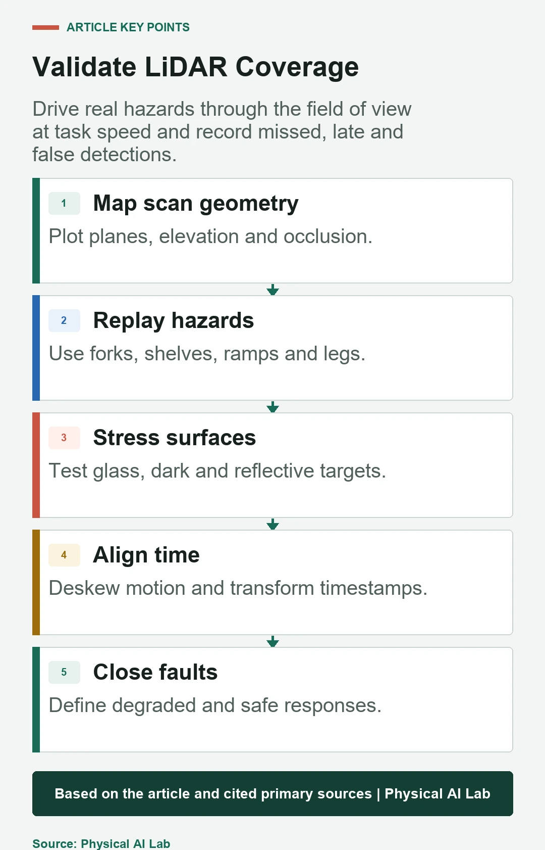
Run the installed robot past forks, overhangs, ramps, people, reflective panels and contamination at task speeds. Measure missed, late and false detections plus localization error, latency, resource margin and maintenance burden. Compare the simplest architectures that satisfy the same evidence target.
Release with a concise checklist.
- Plot installed rays, occlusions and near-field gaps.
- Test every required obstacle across distance and angle.
- Verify timestamps, deskew, transforms and filters.
- Measure worst-case compute and data age.
- Separate task perception from validated protective functions.
Frequently asked questions
Is 3D LiDAR always better for an AMR?
No. It adds height evidence but also cost, processing and failure modes; a planar system may better fit a flat structured task.
Can a 3D LiDAR replace a safety scanner?
Not automatically. A protective function needs an appropriate device, architecture, standards basis and validated stopping behavior.
Does projecting a 3D cloud make it equivalent to 2D LiDAR?
No. The resulting scan retains the original point pattern, timing, density and blind zones.
Will more LiDAR channels detect every small obstacle?
No. Range, angular spacing, incidence, reflectivity, motion and filtering still determine detection probability.
Which dimension detects glass better?
Neither guarantees it. Test the specific wavelength, sensor, glass treatment, angle and environment, and design a failure policy.
Perception Coverage and Safety Boundary
General-purpose LiDAR data is not automatically a safety-rated protective measurement. Perform an application-specific risk assessment and validation.