A robot can appear geometrically miscalibrated when its sensors disagree in time. A moving object, rotating base or swinging arm turns clock offset into spatial error. Time synchronization therefore requires an end-to-end map from physical sampling through device, network, host and ROS timestamps.
NTP and PTP synchronize clocks through different mechanisms and deployment assumptions. Hardware timestamping moves the packet event closer to the network interface, but it does not automatically timestamp sensor exposure. The application must know each clock domain and conversion.
Use this guide with the robot sensor-fusion guide and TF2 coordinate-frame guide. Test failure and recovery, not only steady-state offset.
Suspect time before recalibrating geometry
If a point cloud trails motion, camera and lidar disagree only while moving, or an estimator innovation grows with speed, compare timestamps and data age before changing extrinsics. A fixed time offset produces a motion-dependent spatial bias that static calibration cannot remove.
Recreate the symptom at several velocities and directions. Estimate whether observed displacement matches velocity multiplied by time offset. Preserve raw source stamps and receipt times so later synchronization work can be evaluated against the same data.
Inventory every clock domain
List sensor oscillators, camera or lidar clocks, GNSS time, network-interface PTP Hardware Clocks, host system clocks, accelerator clocks, controller clocks and simulation time. Record epoch, resolution, rollover, reset behavior and which component performs conversion.
A timestamp value without a clock identity is ambiguous. Name the authoritative clock for each data product and state how it relates to the robot system time. Avoid assuming two identical device models share a clock.
| Clock domain | Typical event | Conversion owner | Failure mode |
|---|---|---|---|
| Sensor clock | Exposure or sampling | Driver or firmware | Reset or drift |
| NIC PHC | Packet ingress or egress | PTP stack | Unsynchronized interface |
| System clock | Host application time | phc2sys or NTP | Step or slew |
| ROS time | Message and application time | Node configuration | Mixed sim and wall time |
| Controller clock | Actuation sample | Gateway | Unknown transport delay |
Separate offset, drift and jitter
Offset is the instantaneous difference between clocks. Drift is how that difference changes over time. Jitter is short-term variation in measurement or correction. A small average offset can hide large tails, periodic wander or a step after grandmaster change.
Report distribution, maximum observed value, sampling interval and test duration. Plot offset over temperature and load. Define application thresholds from motion and fusion error, not from a generic synchronization marketing number.
Choose NTP or PTP from the timing path
NTP synchronizes networked system clocks and is widely available. PTP can use hardware timestamping, transparent or boundary clocks and a grandmaster to reduce software and network uncertainty. Actual performance depends on topology, timestamp location, path asymmetry and device support.
RFC 5905 documents NTPv4. PTP deployment should follow supported profiles and equipment. A protocol name does not establish application accuracy; measure at the timestamps the robot actually consumes.
Design grandmaster, domains and failover
PTP participants select or follow a grandmaster within a domain. Decide whether the source is GNSS-disciplined, local or redundant, and how multiple networks or robots are separated. Verify priority configuration and the behavior of the best-master selection process.
Test grandmaster loss, a competing clock, link interruption and return. Record time steps, holdover and convergence. A graceful failover for monitoring may still be unacceptable for sensor fusion if timestamps jump across an episode.
| Test phase | Measure | Injected condition | Application response |
|---|---|---|---|
| Steady idle | Offset and jitter | No load | Normal validity |
| Network load | Tail offset | Competing traffic | Maintain or degrade |
| Clock loss | Holdover drift | Grandmaster removed | Flag uncertain time |
| Recovery | Step and convergence | Grandmaster returns | Quarantine interval |
| Restart | Epoch and monotonicity | Sensor or host reboot | New episode or remap |
Hardware timestamps locate packet events
Hardware timestamping records packet ingress or egress near the network interface, reducing operating-system scheduling uncertainty. Linux exposes PTP Hardware Clock support through its PTP subsystem, but driver and NIC capabilities vary.
The Linux PTP hardware-clock documentation describes the interface. Verify which packets and directions are hardware stamped. A PHC timestamp still represents a network event, not necessarily the physical sensor sample.
Understand ptp4l and phc2sys roles
ptp4l implements PTP for supported network interfaces and can synchronize a PHC to a grandmaster or operate in other clock roles. phc2sys commonly synchronizes the system clock and a PHC. Running one does not prove the other clock is aligned.
Read the current ptp4l and phc2sys documentation for options and profiles. Archive configuration, interface, transport, domain, clock class and log statistics with test results.
Timestamp near physical sampling
The most useful sensor timestamp represents exposure start, exposure midpoint, lidar firing, IMU sample or another defined physical event. A driver timestamp created after USB transfer or processing contains variable delay that clock synchronization cannot remove.
Ask the sensor vendor or inspect driver code to identify the event and clock. Measure transport delay separately. For rolling-shutter cameras or scanning lidars, one timestamp may not describe every pixel or point; downstream algorithms may need per-line or per-point timing.
Validate conversion at the ROS driver boundary
A driver may convert a device tick counter into system or ROS time using an estimated offset. Check units, rollover, startup convergence, clock reset and whether use_sim_time changes interpretation. Preserve both raw and converted values during commissioning.
Reject timestamps far in the future, implausibly old or non-monotonic. Mark time quality in diagnostics. Do not silently replace an invalid hardware stamp with arrival time without recording that fallback.
Test idle, load, loss and recovery
Measure synchronization while the network is idle, under realistic sensor traffic and CPU load, during grandmaster or link loss and through recovery. Include temperature and long duration because oscillator drift and thermal behavior may dominate holdover.
Correlate clock statistics with application outputs such as fusion residuals, transformed point alignment and command age. This proves whether the measured clock performance is sufficient for the robot rather than merely compliant with a tool threshold.
Quarantine data across time discontinuities
When a clock steps, reboots or changes authority, messages around the event may have ambiguous ordering. Define a quarantine interval, reset estimator buffers and prevent old commands from becoming current. Resynchronization does not repair data already stamped under the wrong mapping.
Log the discontinuity as an episode boundary. For training data, retain the failure marker and exclude affected samples through a traceable rule instead of deleting them without provenance.
Accept accuracy and recovery together
An acceptance requirement should state steady-state offset and jitter tails, allowed drift in holdover, detection time, behavior during uncertainty and recovery criteria. Verify every clock path used by required sensors and controllers.
Store topology and configuration with the results.
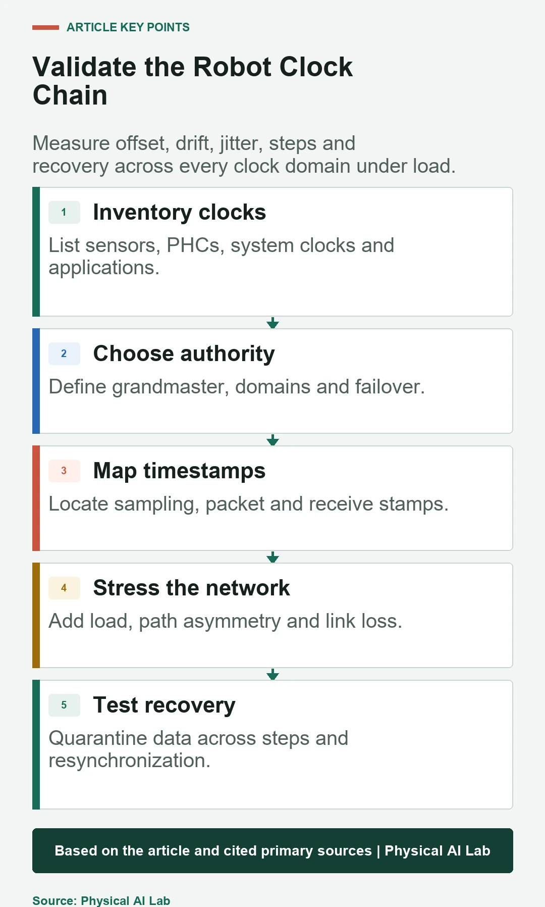
- Inventory all device, PHC, system and ROS clocks.
- Define the physical event behind each timestamp.
- Measure offset, drift and jitter under load.
- Inject authority loss, reboot and recovery.
- Quarantine data across clock discontinuities.
Frequently asked questions
Does enabling PTP align every sensor timestamp automatically?
No. Sensors may use independent clocks or stamp after transport; drivers must map their sample events into the synchronized domain.
Should a robot use NTP or PTP?
Choose from required accuracy, hardware support, topology and failure behavior, then measure the complete timestamp path.
Is a small average offset enough?
No. Tail jitter, drift, clock steps and recovery intervals can still violate the application requirement.
Does ptp4l also synchronize the system clock?
Not necessarily. phc2sys or another mechanism is commonly used to relate PHC and system time.
Can data recorded during loss be used after clocks recover?
Only if its timestamp mapping remains valid. Data across an uncertain or stepped interval should be quarantined and assessed.
Time Synchronization Evidence Boundary
Time synchronization performance is topology, hardware, driver and workload specific. Validate physical sample timing and application error, not only a daemon's offset display.