AMR auto-docking is a sequence, not one pose command. The robot must reach a staging region, identify the intended dock, approach within mechanical tolerances, establish the required contact or coupling, confirm charging, and leave the station predictably. Each phase can succeed while the next fails.
A single success percentage is misleading without the trial population and success definition. Vary initial pose, battery state, payload, floor friction, lighting, target condition and nearby traffic. Report first-attempt success, eventual success, time, contact quality, retries and failure reason separately.
Use this guide with the AMR selection guide and robot time synchronization guide. Confirm electrical and battery requirements with the charger and robot manufacturers.
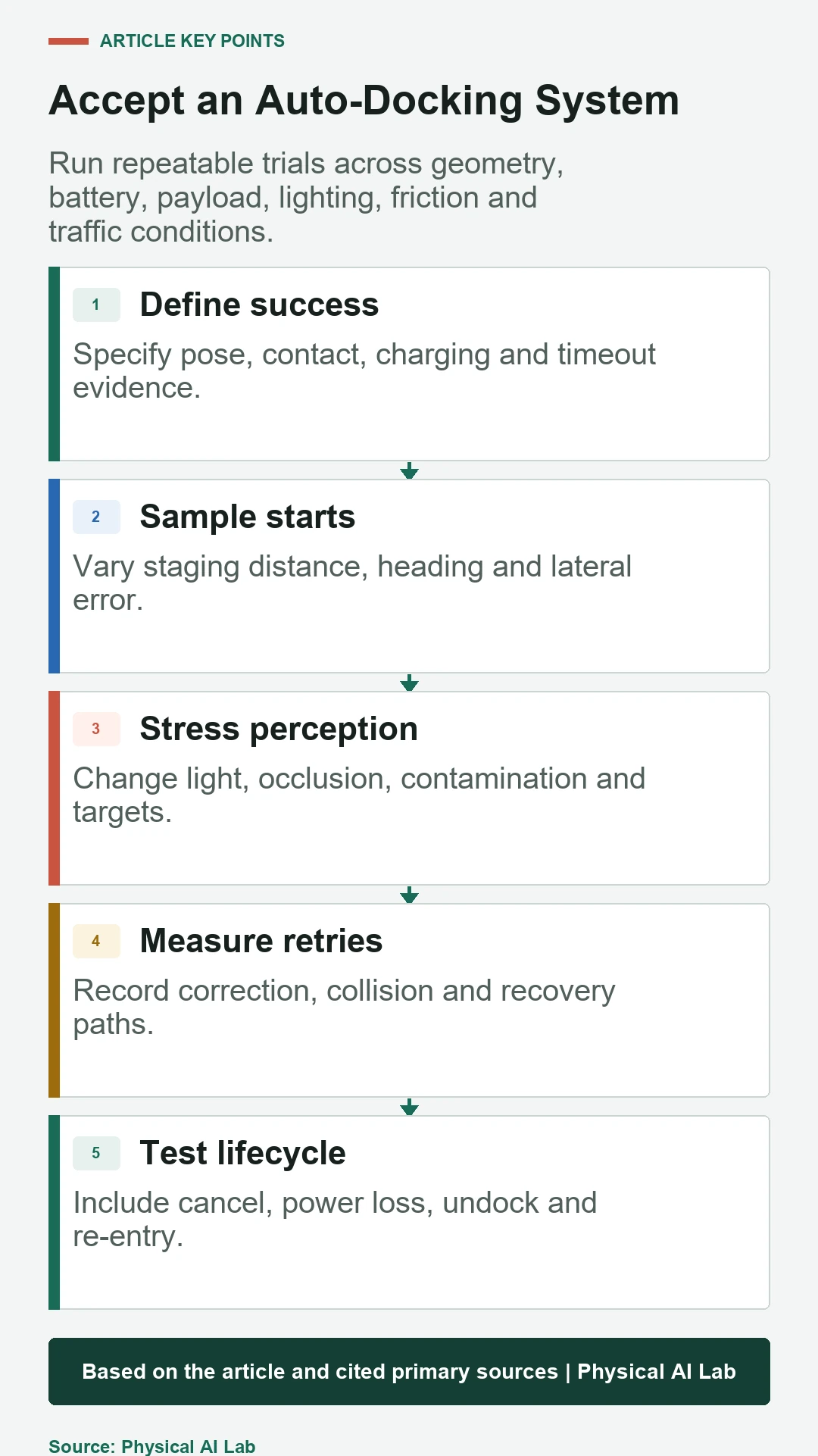
Define docking success as observable states
Separate navigation arrival, dock detection, controlled approach, mechanical contact, electrical contact, charging current and stable charging over time. Decide which state completes the docking action and which state the fleet manager uses to mark the robot available or unavailable.
The current Nav2 Docking Server documentation exposes parameters for staging, detection, control, timeouts and retries. Map each configured behavior to independent telemetry so a generic dock failed result can be diagnosed without replaying video alone.
Create a repeatable staging-pose distribution
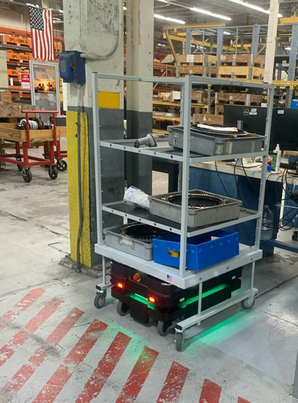
A staging pose places the robot where dock-specific detection and control can begin. Test a distribution of distance, heading and lateral error rather than resetting to one ideal mark. Include errors produced by realistic global navigation and localization, not only manually placed trials.
Define the region from which docking is expected to recover and the region that should be rejected. Randomize trial order to avoid battery, temperature or floor changes correlating with one pose. Save actual starting pose and uncertainty for every run.
| Phase | Success evidence | Primary measurement | Common failure |
|---|---|---|---|
| Stage | Robot inside allowed region | Pose error and arrival time | Navigation or localization miss |
| Detect | Correct dock estimate current | Detection confidence and age | Wrong or stale target |
| Approach | Trajectory remains within envelope | Lateral and heading error | Oscillation or saturation |
| Contact | Mechanical or electrical switch state | Force, switch or connection | Misalignment |
| Charge | Stable accepted power state | Current, voltage and duration | False contact or charger fault |
Verify dock identity before final approach
Sites may contain several visually similar stations. Detection must associate the observed target with the assigned dock and its reference frame. Test adjacent docks, partial occlusion, altered backgrounds and temporary objects. A high-confidence pose for the wrong charger is a dangerous success.
Timestamp detections and define a maximum age. Compare the detector estimate with independent ground truth during validation. When external detection is disabled or unavailable, document which pose source replaces it and how accumulated localization error affects the final approach.
Tune approach control within a physical envelope
Approach speed and control gains must respect mechanical capture range, floor friction, payload, drive kinematics and stopping behavior. Faster convergence can increase impact or overshoot. Define lateral, heading and velocity envelopes at several distances from contact.
Record commanded and measured motion, pose error and controller saturation. Test at low and high payload, worn wheels and representative floor seams. A controller that works after repeated corrections may still be unacceptable for connector wear or aisle occupancy.
Distinguish contact from verified charging
Physical contact does not prove that power transfer began. Contacts may be dirty, misaligned or electrically rejected. Require a charger or battery-management signal, current or another authoritative state, then confirm it remains valid for a minimum duration before declaring success.
Specify debounce and timeout behavior. If current briefly appears and vanishes, classify the run separately from no contact. Do not use battery percentage increase as the only immediate signal because its update period and estimation filters may be too slow for docking control.
| Condition varied | Why it matters | Minimum output | Useful split |
|---|---|---|---|
| Start pose | Tests capture range | Success and approach time | Distance, heading, lateral error |
| Battery state | Changes urgency and acceptance | Charge confirmation | Low, nominal, near full |
| Payload | Changes dynamics and geometry | Contact error and retries | Empty and rated loads |
| Lighting or target | Changes detection | Pose error and false identity | Nominal and degraded |
| Floor and traffic | Changes motion and access | Delay and abort reason | Dry, seam, obstruction |
Design retries around changed evidence
A retry should alter the condition that caused failure: back away to a defined pose, reacquire the dock, reduce uncertainty or choose a controlled offset. Repeating the same approach from the same erroneous estimate consumes time and can repeatedly strike hardware.
Set retry count, total time and cumulative contact limits. Record attempt-level reason and pose. Escalate to another station or maintenance when evidence indicates a charger or connector defect rather than a transient alignment error.
Test cancellation during every phase
Fleet reassignment, emergency operations or operator commands can cancel docking during navigation, detection, approach, contact verification or charging confirmation. Define the resulting command, brake state and reservation ownership for each phase. Cancellation should not leave the robot pushing against the station.
Measure cancel-to-zero-command and physical stop time. Verify that charger enable state and dock reservation are released or retained according to policy. Send a new mission only after the old docking action has acknowledged cancellation and motion ownership is clear.
Include undocking and re-entry
Docking reliability includes leaving the charger without snagging contacts, dragging cables or entering traffic unexpectedly. Define charger disable, mechanical release, initial motion and clearance checks. Verify that the robot can return to normal localization and navigation after leaving.
Test an interrupted undock and a request to dock again shortly after departure. Record station state and reservation transitions. A system that charges reliably but cannot vacate the dock predictably reduces fleet capacity and can block emergency access.
Exercise environmental and maintenance degradation
Add safe, controlled variations in dust, contact contamination, target damage, glare, shadow, vibration, floor reflectivity and nearby obstacles. Track contact wear and station alignment over repeated cycles. Maintenance-related drift often appears gradually rather than as one obvious failure.
Establish inspection thresholds from measured degradation. Link failure codes to work orders where practical. Avoid changing controller tolerance to accommodate a mechanically shifted charger without identifying and correcting the physical cause.
Measure station occupancy and fleet impact
Docking time consumes a shared resource. Measure queue delay, approach occupancy, charging confirmation time, failed-attempt blockage and time to clear the station. A small increase in eventual success may reduce fleet throughput if retries monopolize the charger.
Model station reservations and release conditions with the fleet allocator. Test robot and charger faults while another robot waits. Keep safety separation and traffic rules outside a purely throughput-driven optimization.
Build an automated trial record
For every trial, store software and parameter versions, robot and dock identity, start pose, battery, payload, environment class, timestamps, detection stream, commands, contact signals, charge evidence, attempts and final reason. Attach video only as supporting evidence, not the sole record.
Automate checks for missing signals, inconsistent clocks and impossible state order. Use the same schema for laboratory and field trials so regressions can compare conditions rather than hand-written labels.
Release with confidence intervals and failure detail
Report first-attempt and eventual success with trial counts and uncertainty, plus median and tail docking time. Break down failures by phase and condition. A claim based on many repetitions of one ideal pose should not be generalized to the operational staging region.
Use a release checklist that includes the full lifecycle.
- Declare physical and electrical success evidence.
- Sample the realistic staging-pose distribution.
- Measure first attempts, retries and total occupancy.
- Test cancel, power loss, undock and re-entry.
- Preserve phase-specific reason codes and timing.
Frequently asked questions
Is reaching the dock pose a successful docking event?
No. Success normally requires the specified contact or coupling and authoritative confirmation that charging began and remained stable.
How should auto-docking success rate be reported?
State the trial population, first-attempt and eventual success, counts, timing and phase-specific failure reasons.
How many docking retries are reasonable?
Set count, total time and contact limits from measured effectiveness, wear, station occupancy and operational risk.
Should battery percentage confirm charging?
Usually not by itself. Use a charger or battery-management state, current or another timely authoritative signal.
Why test undocking in a docking study?
A station is not operationally available until the robot can disconnect, clear it and return to navigation predictably.
Docking Success and Electrical Safety Boundary
Docking involves robot motion, electrical power and battery systems. Use manufacturer requirements and appropriate safeguards; software success signals do not establish electrical safety.