Three rectangular robot-link sections can all have approximately 144 mm² of area and still produce very different area moments about the same world axes. In my Blender comparison, a 24 × 6 mm section had Jxx ≈ 432 mm⁴ and Jyy ≈ 6,912 mm⁴ at zero degrees. In the independently authored 45-degree state, both diagonal components were about 3,672 mm⁴, with a large signed off-diagonal term. A 12 × 12 mm square kept nearly equal diagonal components at either orientation.
The immediate design lesson is that equal area does not replace a selected-axis section calculation. Width, depth, orientation, and the axes in which the components are expressed all matter. Area alone may help compare material quantity in a simplified extrusion, but it cannot tell me how the same finite section distributes that area around a chosen centroidal axis.
I built six independently authored static prisms in an AI-operated Blender 5.2.2 LTS session on October 8, 2026. Each prism was 80 mm long. The cross-sections were 24 × 6, 12 × 12, and 6 × 24 mm, each at 0 and 45 degrees about the common Z direction. This was a geometry experiment. It was not a deformation simulation, finite-element analysis, material test, or robot-link load test.
Equal area preserved one number and changed the others
The three input areas are nominally the same: 24 × 6, 12 × 12, and 6 × 24 all give 144 mm². The areas recovered from the actual world-space cap polygons ranged from 143.999868 to 144.000315 mm². I therefore describe them as approximately equal rather than pretending that the captured binary coordinates produced one exact decimal value.
For each section, I used centroidal area moments in fixed world X and Y directions:
Jxx = ∫(y - cy)² dAJyy = ∫(x - cx)² dA- signed off-diagonal
Jxy = -∫(x - cx)(y - cy) dA
These are two-dimensional geometric quantities with units of mm⁴. They are not the three-dimensional mass-inertia tensor of the prism, and no density or mass was assigned. The separate rigid-body inertia experiment deals with mass distribution, reference points, and axes in a 3D inertia tensor. Copying its kg·m² interpretation into this table would be a category error.
The unrotated wide and tall sections make the selected-axis effect obvious. The 24 mm horizontal width puts relatively little area far from the world X axis, so Jxx is about 432 mm⁴, while Jyy is about 6,912 mm⁴. Swapping width and height swaps which diagonal component is large. The area remains approximately 144 mm² in both cases.
The actual six-section comparison
| Section | Angle | Jxx (mm⁴) | Jyy (mm⁴) | Signed off-diagonal (mm⁴) |
|---|---|---|---|---|
| 24 × 6 mm wide | 0° | 431.999 | 6911.997 | 0.000 |
| 24 × 6 mm wide | 45° | 3671.999 | 3671.999 | -3239.999 |
| 12 × 12 mm square | 0° | 1727.997 | 1727.997 | 0.000 |
| 12 × 12 mm square | 45° | 1727.999 | 1727.999 | 0.000 |
| 6 × 24 mm tall | 0° | 6912.017 | 432.003 | 0.000 |
| 6 × 24 mm tall | 45° | 3672.000 | 3672.000 | +3240.000 |
The table rounds the actual polygon integrations to three decimals for readability. Those decimals are numerical reporting, not physical measurement accuracy. The underlying calculation used the finite cap boundaries recovered from evaluated world-space vertices, not ideal rectangles substituted after the fact.
The 45-degree wide and tall sections show why the off-diagonal term belongs in the comparison. Both diagonal components become approximately equal in the fixed world axes, but that does not make either section isotropic. Their large off-diagonal terms have opposite signs because the two elongated rectangles lean in opposite geometric senses relative to X and Y. Dropping that term would hide the orientation of the section’s preferred directions.
The square behaves differently. At zero degrees, both diagonal components were 1727.996841 mm⁴. At 45 degrees, they were 1727.999431 and 1727.999052 mm⁴, with an eigenvalue gap of only about 0.000379 mm⁴. The experiment declared any gap within 0.001 mm⁴ directionally indeterminate. It would therefore be misleading to claim a stable preferred principal direction from that tiny captured difference.
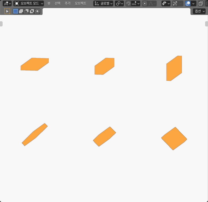
Rotating the section changes world-axis components
For an ideal rectangle, rotating the same section changes its component matrix in fixed axes while preserving its principal values. The 0-degree wide section has one small and one large principal value. At 45 degrees, those values are redistributed into equal diagonal terms and nonzero off-diagonal terms. The tall section shows the complementary sign.
That ideal transformation is a useful mathematical cross-check, but it is not permission to force the actual captured intervals to be identical. The Blender world coordinates are finite binary values, and the six cells use different display translations. The actual areas and recovered eigenvalue intervals therefore differ slightly between nominally rotated copies. I kept those differences instead of replacing them with ideal values.
For the wide section, the actual 0-degree eigenvalue intervals were approximately 431.999411–431.999412 and 6911.997021–6911.997022 mm⁴. At 45 degrees they were approximately 431.999762–431.999763 and 6911.997724–6911.997725 mm⁴. They are close in the way the ideal rotation predicts, but they are not the same actual intervals.
The same caution applies to the tall pair. Its actual 0-degree values were close to 432.002697 and 6912.017406 mm⁴, while the rotated pair’s principal values were close to 432.000308 and 6911.999620 mm⁴. I use ideal rotation invariance to check the pattern, not to erase the finite captured coordinates.
The University of Alberta’s rectangular area-moment explanation was checked on October 8, 2026 and provides the standard centroidal definitions and rectangle formulas behind this interpretation. My experiment independently integrated the actual finite polygons. The source does not validate these Blender meshes, a robot link, or a physical bending result.
How I measured the finite cap polygons
Each model was a closed rectangular prism with eight vertices, six quad faces, and twelve native triangles after evaluation. The 80 mm extrusion direction was parallel to world Z in every case. I recovered the lower and upper four-point end polygons from the actual outward cap boundaries and checked that corresponding points formed the same section at both ends.
The cap area, centroid, and central moment matrix were integrated from the ordered world-space polygon. A second calculation integrated the actual cap triangles. For each cap, the polygon and actual-triangle integrations returned the same rational integrals for the captured coordinates. The upper and lower caps also agreed. Across the experiment, 48 actual vertices and 72 actual triangles were checked through three complete reads and a distinct representative read.
The section centroids came from the polygon integration, not from an assumed object origin. That detail matters because display placement should not change a central area moment. The upper and lower rows of models were spaced 100 mm apart for visibility. That spacing is not a support span, link offset, or assembly dimension and was removed from the central calculation.
The model used 4-micrometre coordinate and 8-micrometre comparison allowances to check captured geometry against the authored recipe. Those are numerical consistency bounds, not manufacturing tolerances or metrology accuracy. The rational polygon integration and its decimal enclosures describe the captured model only.
Area moment is not stiffness, strength, or load capacity
The experiment deliberately stops at section geometry. The sections are solid rectangles, with no hollow-wall model. The experiment assigns no elastic modulus, density, material direction, joint interface, fastener, or load. It contains no deflection solver, stress field, buckling mode, fatigue cycle, or physical support.
That boundary prevents a tempting but unsupported conclusion. The wide rectangle’s two principal geometric moments differ by roughly a factor of 16 in the ideal rectangle calculation, but this experiment does not claim 16 times the stiffness, capacity, or performance of a robot link. A bending response also depends on material, load direction, boundary conditions, length, connections, local features, and the question being asked.
The overhung-shaft reaction experiment makes a complementary point: load-path signs and support assumptions must be preserved before using calculated reactions elsewhere. The current experiment does not apply those reactions to a section. It isolates the geometric tensor that a later, properly scoped analysis might use.
The 80 mm prism length is likewise not evidence about a beam’s installed span. Area moments are properties of the end section in the chosen axes. The length only makes the six closed solids easy to inspect as finite Blender objects. No support or force is attached to either end.
Use a selected-axis check before comparing link sections
For a practical geometry review, I would record five items together: section shape, area, centroid, expression axes, and the full symmetric area-moment matrix. If the design has a known bending plane, compare the component about the corresponding centroidal axis. If the section or load direction rotates, transform the full matrix or recompute it in the common axes instead of carrying over one scalar.
The six Blender cells suggest a compact diagnostic sequence:
- Confirm that the candidate sections really have the intended finite boundaries and approximately equal area.
- Recover the actual centroid rather than assuming it lies at a modeling origin.
- State the common axes used to express
Jxx,Jyy, and the signed off-diagonal term. - Check principal values and the eigenvalue gap without inventing a preferred direction for a nearly isotropic section.
- Only then combine the geometric result with separately justified material and loading assumptions.
This sequence catches two opposite mistakes. One is treating equal area as equal selected-axis geometry. The other is treating equal diagonal components after a 45-degree rotation as proof of an isotropic section while ignoring the off-diagonal term. The square is the useful control: its diagonal values remain nearly equal and its tiny principal-value gap stays below the experiment’s direction threshold.
The direct result is narrower than a strength claim and more useful than an area-only comparison. All six actual sections had approximately 144 mm² of area, yet their world-axis area moments ranged from about 432 to 6912 mm⁴, and rotating the elongated rectangles created signed off-diagonal terms near ±3240 mm⁴. Equal area did not preserve the geometric quantity needed for a chosen bending-axis calculation.