Oldham coupling offset needs a finite engagement check at both perpendicular sliding interfaces. In my AI-operated Blender 5.2.2 LTS model, a 6 mm X offset reduced lower overlap from about 16 to 12 mm while upper overlap stayed at 16 mm. A 6 mm Y offset swapped the affected interface. At 22 mm X, lower overlap was zero and upper overlap was still 16 mm. These are static measurements of generic authored shapes, not operating limits for a commercial coupling.
The useful design question is therefore directional: which interface absorbs a proposed offset, and how much finite tongue remains between its rail end planes? A coupling can retain one apparently healthy interface while the orthogonal interface is only partly contained or has no longitudinal overlap at all. That distinction belongs in the geometry review before torque, wear, speed, or allowable misalignment enters the discussion.
One offset direction consumed one interface
An Oldham-style arrangement uses three rigid assemblies and two perpendicular sliding connections. The MISUMI overview of Oldham couplings, checked on October 8, 2026 UTC, describes that basic architecture. I used that limited concept only. The Blender parts were my own rectangular proxies, with no manufacturer dimensions, ratings, bores, shafts, fasteners, or round commercial discs.
The lower tongue was 16 mm long along X and moved within a 20 mm-long lower groove. The upper tongue had the same lengths but slid along Y. This left a nominal 2 mm end margin at each end when centered. The two rail pairs also provided about 0.5 mm of side clearance in their respective section planes. Each tongue entered its interface by 3 mm in the normal direction, with about 0.5 mm between its tip and the center web.
Those transverse and normal dimensions did not answer the longitudinal engagement question. When the center moved 6 mm in X relative to the lower hub, the lower tongue still overlapped the groove by 12 mm, but one of its containment margins became -4 mm. The negative margin means the finite tongue extended beyond a groove end plane; it does not mean the tongue disappeared. Because the upper hub moved with the center in that case, its Y-directed interface kept the centered 16 mm overlap and approximately 2 mm end margins.
For the Y case, I held the lower hub and center assembly fixed and moved only the upper hub 6 mm along Y. For the X case, the center and upper hub moved together, while the lower hub stayed fixed. The slide orientations were held fixed in all four cells. The equal offset magnitudes therefore consumed different interfaces in this comparison; I did not rotate the mechanism through a revolution.
The same offset magnitude gave different overlap
On October 9, 2026 KST, I used an AI-operated Blender 5.2.2 LTS session to author four independent static cells: centered, +6 mm in X, +6 mm in Y, and +22 mm in X. Each cell contained nine unshared closed rectangular prisms: two members for the lower hub, five adjacent members for the center assembly, and two members for the upper hub. The five center members met at boundary planes; they were not Boolean-unioned into a manufactured center disc. Across the four cells, the actual scene contained 36 closed meshes, 288 evaluated vertices, and 432 native triangles.
I recovered each groove’s inner side faces, web face, and finite end planes from the evaluated world-space vertices. The engagement calculation intersected the tongue and groove intervals along the appropriate slide axis. A separate containment calculation compared both tongue ends with both groove ends. The model also checked the transverse gaps, insertion overlap, tip-to-web gap, and every member pair for positive interior volume. None of the 144 box pairs had positive interior overlap in these four authored states.
The table rounds the measurements to match the design question. “End margin” is the smaller of the two signed containment margins. A negative value means a tongue end crossed a finite groove boundary.
| Case | Applied offset | Lower overlap / end margin | Upper overlap / end margin | Geometric reading |
|---|---|---|---|---|
| Centered | 0 mm | 16 mm / +2 mm | 16 mm / +2 mm | Both tongues fully contained |
| X shift | +6 mm X | 12 mm / -4 mm | 16 mm / +2 mm | Lower partial; upper contained |
| Y shift | +6 mm Y | 16 mm / +2 mm | 12 mm / -4 mm | Lower contained; upper partial |
| X withdrawn | +22 mm X | 0 mm / -20 mm | 16 mm / +2 mm | Lower has no finite overlap |
The coordinate and comparison bands used to check the authored model were 4 and 8 micrometres. They are numerical consistency bounds for this scene, not machining tolerances, product accuracy, or permissible shaft misalignment. The public values above are rounded to dimensions that match the design question.
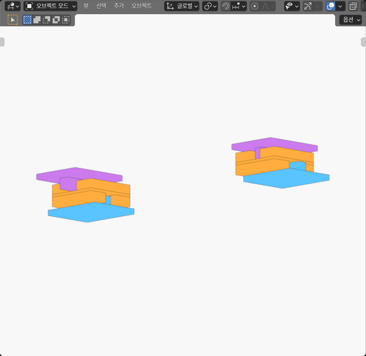
Overlap and containment answer different questions
The 12 mm value in each 6 mm case is positive finite overlap. It says the tongue and groove still share a longitudinal interval. It does not say the tongue remains fully captured within the authored 20 mm groove. The -4 mm end margin shows why: one tongue end lies 4 mm beyond the corresponding groove end plane.
This distinction changes the review sequence. First ask whether overlap is positive. Then ask whether both ends remain within the finite groove. If full containment is a requirement of the model, a partially overhanging tongue fails that declared criterion even though its remaining overlap is substantial. If a real design permits overhang, the next questions would concern edge loading, material, stress, wear, and retention. This static geometry experiment did not answer those questions, so it cannot convert “12 mm remains” into an allowable operating state.
The centered cell satisfied the model’s full-containment criterion at both interfaces. The X-shift and Y-shift cells each satisfied it at one interface and missed it at the other. The withdrawn cell made the difference even clearer: the lower overlap fell to zero while the orthogonal upper interface remained centered. Checking only the healthier interface would miss the loss of the other connection.
This is related to, but separate from, the assembly-route question in the dovetail end-loading experiment. That study asked whether a rigid insert could reach a valid seated fit through a finite opening. Here the three assemblies are already staged, and the question is how much of each perpendicular sliding interface remains under a specified parallel offset.
The 0.5 mm section gaps are not the withdrawn distance
The model’s roughly 0.5 mm side gap and roughly 0.5 mm tip-to-web gap describe different section-plane relationships. They are useful for confirming that the tongue is not already touching a rail side or the web in the centered and partially engaged states. They are not a substitute for finite three-dimensional distance after longitudinal withdrawal.
In the +22 mm X cell, the lower tongue and lower groove no longer overlap along X. Their nearest solid separation includes the end gap created by that withdrawal. Reporting the section-plane 0.5 mm value as the nearest three-dimensional solid gap would therefore be wrong: the relevant shapes are separated longitudinally before a side or web clearance can become the limiting distance.
This is an easy modeling error when a section drawing is treated as if it describes every spatial state. A cross-section can establish width clearance and insertion depth where the members share a longitudinal interval. Once that interval is empty, distance must be measured between the actual finite solids. The same rule applies when a tongue is shorter than a rail, when a slider has moved past a guide, or when an apparently valid two-dimensional clearance is located outside the part’s finite length.
Static geometry does not prove torque transfer
All four cells were independently authored poses, not frames from a simulated stroke. I did not rotate shafts, drive a center member, solve contact, or measure force. The scene contained no physical pins, bearings, friction, backlash, elastic deformation, lubrication, or wear. It also did not test how an offset evolves through a revolution. The positive-overlap states are geometric observations, not evidence that a coupling can transmit a requested torque.
The absence of positive interior volume among the 144 member pairs is similarly narrow. It confirms that these particular axis-aligned box members did not occupy the same interior volume in the captured poses. It does not establish safe operation, adequate edge support, or a suitable commercial coupling. Shared boundary planes among adjacent center members are part of the authored construction, not contact results.
Static position also leaves out approach history. The separate gearbox backlash experiment examines how one input coordinate can correspond to different output states after reversal. That is a different prescribed gearbox model; its numbers do not describe this Oldham arrangement. Here I checked neither rotating transmission nor backlash. The result is limited to finite static engagement at four authored offsets.
A practical two-interface review
Start with the actual finite lengths, not just an offset rating or a centerline sketch. For each interface, record the tongue interval and the groove interval along its own slide axis. Compute their overlap, then compute both signed containment margins. Repeat the process for the perpendicular interface. A single radial magnitude should be decomposed into the two component directions before either interface is judged.
For a tongue interval [t0, t1] and groove interval [g0, g1], the overlap runs from the larger starting coordinate to the smaller ending coordinate. Its length is zero if that interval is empty. The two signed end margins are t0 minus g0 and g1 minus t1. Full containment requires both margins to be nonnegative. Keep the signs: taking an absolute value would turn an overhang into an apparent positive reserve.
Next, keep the section-plane checks separate. Measure rail-side clearance, normal insertion, and tip-to-web clearance only where the members share the relevant finite interval. If overlap reaches zero, switch to a finite-solid distance calculation instead of carrying a cross-sectional gap into a spatially withdrawn state.
Finally, state the acceptance rule that belongs to the model. Positive overlap, full containment, and adequate load-bearing engagement are three different claims. This experiment directly checked the first two and used full containment as a declared geometric criterion. It did not define adequate load-bearing overlap.
The actionable result is modest but important: inspect both perpendicular connections independently. In this model, +6 mm X and +6 mm Y had the same scalar magnitude and different affected interfaces. At +22 mm X, one interface had no finite overlap while the other still looked centered. That is enough to catch a misleading “one offset, one engagement” assumption before a more detailed coupling model or physical test begins.