A cable-carrier’s bend radius does not describe its outside clearance. At the end of our 200 mm slide stroke, the centerline remains inside the enclosure, but the specified carrier envelope crosses the end wall by 2.168 mm. The selected loop length and bend radius are unchanged during the stroke; checking the line alone misses the outside boundary.
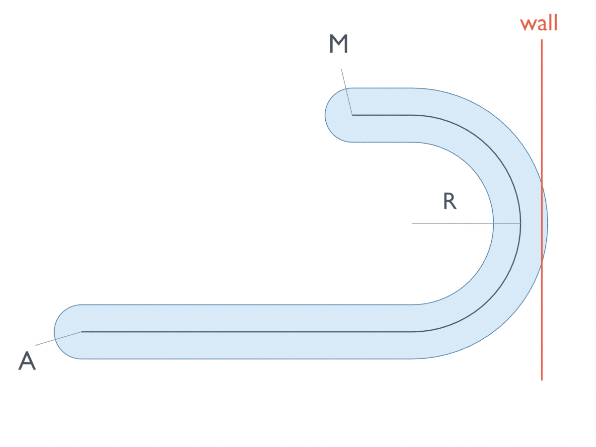
The results and images come from an AI-operated virtual geometric study in Blender 5.2.2 LTS on October 5, 2026, checked against an independent continuous calculation. The loop is prescribed rather than formed by a cable’s weight, stiffness or load; no physical carrier was tested. That distinction matters when comparing two plausible changes: moving the fixed anchor to shorten the route, and shrinking the enclosure. In this example, the first change does not create room for the second.
Where the wall clearance disappears
Picture a fixed endpoint A at (100,0) mm and a moving endpoint M at (x,80) mm. The moving X coordinate runs from 0 to 200 mm. From A, the route travels right along a horizontal straight, turns upward through a right-facing semicircle of centerline radius 40 mm, then returns left along the upper straight to M. Its centerline length stays at 270 mm.
The envelope extends 10 mm around that line in the plane, with rounded endpoint caps. The study also specifies a 30 mm out-of-plane width, but checks installation clearance only in X and Y. It does not reproduce the links, mounting brackets or complete outside shape of a commercial carrier.
In the initial installation box, x spans −15 to 280 mm and y spans −15 to 95 mm. The complete stroke has a minimum envelope clearance of 5 mm. Move only the right wall to x=270 mm and the starting pose still looks clear. The envelope first touches the wall at x≈195.664 mm, then crosses it during the final approximately 4.336 mm of travel.
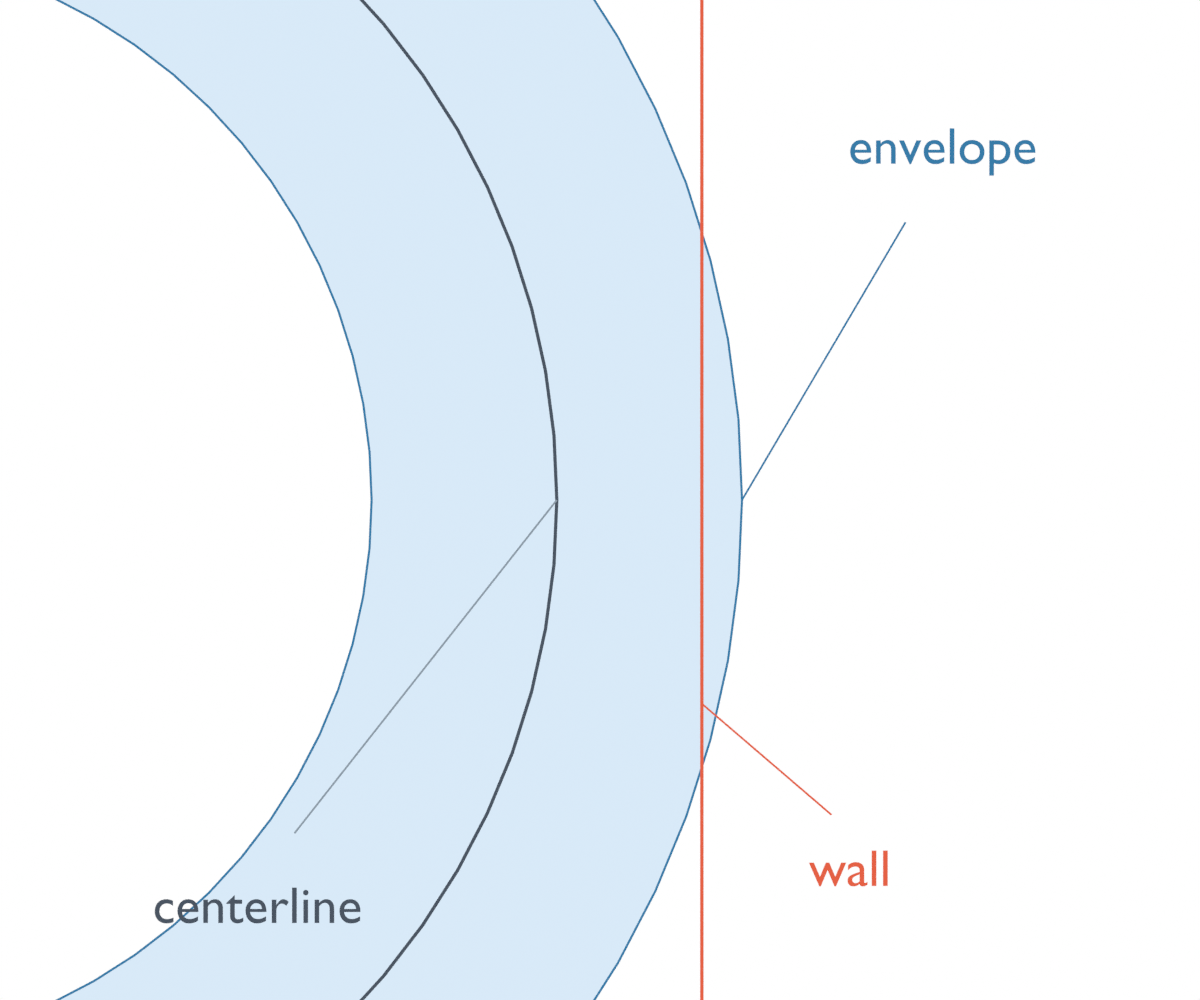
That late crossing is why an inspection of the home position is insufficient. For this particular route the bend advances by half the moving endpoint’s displacement, so its rightmost point can be tracked continuously. The result is not an inference from a few clear screenshots. Zero clearance is the contact boundary; positive clearance lies before it and geometric overlap after it.
The same omission can happen vertically. The centerline occupies y=0 through 80 mm and fits within a 90 mm-high space from y=−5 to 85 mm. The finite envelope occupies y=−10 through 90 mm, crossing both limits by 5 mm. A check of the line would accept a space that is too short for the stated envelope.
Even that 100 mm ideal envelope height is not a product installation-height recommendation. Igus’s chain-length and camber guidance directs that check to the selected carrier’s camber-aware dimension HF. Our smooth loop has no camber or sag. Its radius is measured to its own ideal centerline, so it also needs to be distinguished from the reference used in a product drawing.
An anchor change that leaves the bend in place
Now compare the centered fixed anchor, a=100 mm, with a fixed anchor at the start of the stroke, a=0. Select a 370 mm loop for the end-mounted version instead of 270 mm. Across the complete stroke, both have a shortest end straight of 22.168 mm.
That exceeds the study’s assumed 20 mm straight reserve by 2.168 mm. The reserve is an input chosen for this comparison, not a manufacturer’s requirement or a verified mounting-bracket dimension. With that assumption, the ideal minimum lengths are approximately 265.664 mm for the centered anchor and 365.664 mm for the end anchor; the selected lengths sit just above those bounds.
Why do the two routes still reach the same wall? Call the X coordinate where the straight sections join the bend B. The lower straight is B−a, the upper straight is B−x, and the semicircle uses πR of length. Keeping their total at L gives B = (L − πR + a + x) / 2.
The two arrangements have the same L+a: 270+100 and 370+0. Their bend therefore occupies the same position at every moving-end position. Both sweep x=−10 through approximately 272.168 mm and y=−10 through 90 mm. Moving the fixed anchor to the middle removes 100 mm from one straight run while leaving the critical rightward envelope unchanged.
This is a useful separation to retain on the drawing: one change reduces required route length; a different constraint determines the enclosure boundary. Igus likewise distinguishes centered and offset fixed-end length calculations, but its bend allowance K comes from the selected series. The ideal πR arc and assumed straight reserves here must not replace that catalog allowance.
A negative straight is not another usable loop shape
Keeping the short 270 mm length while moving the fixed anchor to a=0 produces a different failure. The upper straight shrinks to the assumed 20 mm reserve at x≈104.336 mm and to zero at x≈144.336 mm. At the final position its signed length would be −27.832 mm.
That negative value rejects the prescribed right-facing U-loop. It is not a physical straight segment, a sharper bend or a cable stretch result. The short end-mounted control consequently has no valid full-stroke envelope margin; it must not be recorded as zero clearance or illustrated as a functioning route beyond the zero-tail boundary. A different cable shape might be a separate model, but it was not calculated here.
The distinction from the wall case is practical. The wall case retains positive straight lengths and the chosen radius but exceeds the available space. The short control runs out of the geometry required to construct this particular route. Increasing enclosure space alone would not repair that length condition.
Reproduce the five layouts
As a separate readback check, we evaluated four finite envelopes and a marker-only short-loop control in 210 prescribed positions each, including exact boundary probes. An independent script matched their recorded geometry to the continuous calculations. Frames index slide positions, not time; the close numerical agreement does not establish machining accuracy.
The standard-library Python below uses millimetres and the continuous extrema over x=0 through 200 mm. It reports the shortest straight, the remaining margin against the assumed 20 mm reserve, and the worst envelope clearance where a complete route exists. Its code is unchanged from the executed calculation; the prose rounds results to about three decimals.
from math import pi

R, c, stroke, reserve = 40.0, 10.0, 200.0, 20.0
for name, a, L, box in [
    ('center', 100.0, 270.0, (-15, 280, -15, 95)),
    ('end, longer', 0.0, 370.0, (-15, 280, -15, 95)),
    ('right wall', 100.0, 270.0, (-15, 270, -15, 95)),
    ('low height', 100.0, 270.0, (-15, 280, -5, 85)),
    ('end, too short', 0.0, 270.0, (-15, 280, -15, 95)),
]:
    tail = (L - pi*R - max(abs(a), abs(stroke-a))) / 2
    if tail < 0:
        print(f'{name}: minimum signed tail {tail:.3f} mm; no full-stroke U-loop')
        continue
    right = (L - pi*R + a + stroke)/2 + R + c
    left, bottom, top = min(a, 0)-c, -c, 2*R+c
    margin = min(left-box[0], box[1]-right, bottom-box[2], box[3]-top)
    print(f'{name}: min tail {tail:.3f} mm; reserve margin {tail-reserve:.3f} mm; '
          f'envelope margin {margin:.3f} mm')

wall_contact_x = 2*(270-R-c) - (270-pi*R) - 100
print(f'Right-wall contact at x={wall_contact_x:.6f} mm')
print(f'End-anchor short route: 20 mm reserve ends at x={270-pi*R-40:.6f} mm')
print(f'End-anchor short route: zero tail at x={270-pi*R:.6f} mm')
For a layout review, the useful pair of dimensions is the shortest end straight and the farthest outside boundary, evaluated over the same stroke. Record their endpoint and radius conventions beside them. A center point also misses the material boundary in finite-pin containment within a moving yoke slot; the U-loop additionally ties its two straight lengths together through the fixed total length.
The result identifies which geometric condition fails. Actual carrier selection still needs its link geometry, fill, strain relief, guide arrangement and installation requirements. None of those effects, nor out-of-plane obstacles or operating life, is established by this planar envelope calculation.