Two locating holes can each be larger than their pins and still fail to fit the pair. The distance between the holes matters too. In the ideal planar locating geometry below, 100 mm pin spacing and 100.10 mm hole spacing cannot fit two 9.96 mm round pins into 10 mm holes. A specifically relieved second pin fits the prescribed pose, but turning that same pin by 90° loses the benefit. Its relief must accommodate the spacing error in the correct direction.
On October 5, 2026, we ran this AI-operated virtual experiment in Blender 5.2.2 LTS and independently checked the evaluated finite pin meshes in 19 prescribed configurations. The exact ideal calculations and native coordinate readbacks are distinguished below. These are specified test inputs, not measurements of manufactured pins, insertion-force tests or a recommendation for machining a catalog replacement.
Give the second locator a different job
Carr Lane’s diamond-pin locating principles describe pairing a primary round locator with a relieved secondary locator. The round pin provides two-axis location; the secondary is intended to locate in one axis and avoid redundant location. The manufacturer principle explains why the second locator’s geometry and orientation matter. It does not supply the numerical results or test shape used here.
Take X along the line joining the two fixture pins, with Y transverse to that line. A tightly fitting second round pin repeats the spacing constraint already implied by the primary pin and the part’s two-hole pattern. Removing material from the second pin’s X-facing sides can accommodate a spacing difference while retaining more of its Y extent. Rotating that relief changes which direction receives the extra room.
This is a locating decision, rather than a request to make every fit looser. A smaller round second pin creates room in both directions. That may accommodate the hole spacing, but it also changes the transverse allowance.
Define the profile before comparing the fit
Both holes have radius H=5.00 mm. The primary round pin has radius R=4.98 mm, giving 0.02 mm radial clearance when its hole is centered. The main comparison keeps that first hole centered, holds the part without in-plane yaw, and puts the second hole 100.10 mm away. The second fixture pin remains at 100.00 mm, so its hole has a +0.10 mm X offset.
The relieved test profile starts with a radius 4.98 mm disk and retains only the material between X=−0.50 and +0.50 mm. In notation, it is the intersection of x²+y²≤R² with |x|≤a, where a=0.50 mm. Its top and bottom remain circular arcs; its two sides are straight flats. The profile is extruded 8 mm along the hole axis.
This deliberately specified shape represents a directional-relief principle. It is not the drawing of a Carr Lane diamond pin, and its narrow section has not been checked for strength. Actual product geometry, fits and material requirements must come from the selected hardware’s documentation.
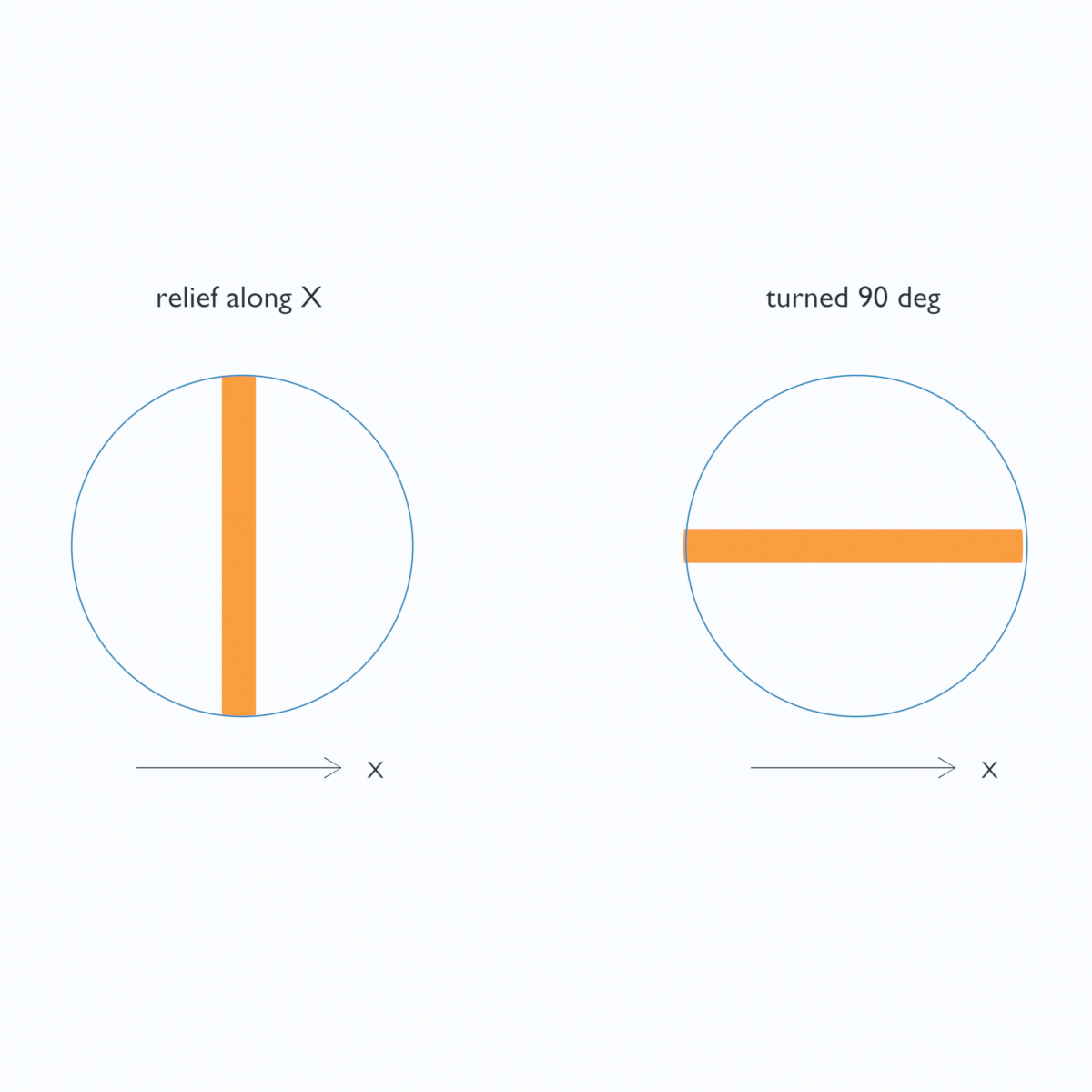
We calculate radial containment margin: the hole radius minus the distance from the hole center to the farthest point on the pin boundary. Positive means that every point fits inside the ideal circular aperture. Zero is exact contact. Negative means that some pin geometry lies outside the aperture; it is not a measured contact force or physical penetration depth.
| Secondary test profile | Ideal second-hole radial margin at +0.10 mm spacing error | Geometric result for this pose |
|---|---|---|
| Round, radius 4.98 mm | −0.080000 mm | Outside aperture |
| Relieved along X, radius envelope 4.98 mm | +0.008968 mm | Positive clearance |
| Same relieved profile rotated 90° | −0.080000 mm | Outside aperture |
| Smaller round, radius 4.80 mm | +0.100000 mm | Positive clearance |
The table gives the continuous ideal calculation. Native world-coordinate readback gave −0.080004, +0.008963, −0.080004 and +0.099994 mm respectively for these four second-hole margins. An independent script reconstructed every evaluated pin vertex and aperture marker, checked the recorded mesh topology and transforms, and compared all 19 configurations with the continuous boundary maximum. Its greatest margin discrepancy was below 0.000008 mm. The 0.00005 mm classification band handles numerical readback around exact contact; it is not a manufacturing tolerance. All cases are static assembled poses at frame 1, not an insertion trajectory.
The table reports the second hole only. The first hole retains its 0.02 mm radial margin in all four rows, so the smaller-round arrangement’s minimum margin across both holes is 0.02 mm, not 0.10 mm.
Why sharing the first hole’s clearance cannot rescue two round pins
Centering the first hole is an explicit comparison pose, not the only pose a part might take. A fair objection is that the part could shift a little and share the two holes’ clearances.
That helps only up to a limit. For two round pins, each pin center must lie within 0.02 mm of its hole center. The difference between the two center spacings cannot exceed the sum of those distances: 0.04 mm. This triangle-inequality bound also holds if the part translates or rotates in its plane.
At a 0.04 mm spacing mismatch, shifting the part by −0.02 mm along X puts both pairs at exact contact. At 0.10 mm, an equal sharing shift of −0.05 mm still leaves both with a −0.03 mm margin. The failure is therefore not an artifact of forcing the first hole to remain centered.
For the relieved example, the stated fit and limits apply to its prescribed no-yaw poses. We have not solved for every possible part pose, clamping sequence or locating repeatability.
Relief has a finite limit, and the two errors interact
For an X offset d≥0, the relieved profile’s farthest points are the junctions between its flats and circular arcs. Their distance from the hole center gives:
margin = H − sqrt(R² + d² + 2ad)
The centered-primary X-offset limit is therefore:
d_limit = sqrt(a² + H² − R²) − a
For the chosen dimensions, the limit is approximately 0.170522 mm. Relief does not permit unlimited travel in X. Equality is contact, not a usable positive allowance.
The transverse result needs its own condition. At zero spacing error, the relieved pin still reaches ±4.98 mm in Y, so a pure Y offset is limited to 0.02 mm. The smaller round radius 4.80 mm pin permits a centered pure Y offset of 0.20 mm. That difference is the cost of simply shrinking the entire second pin in this model; it is not a measured accuracy specification.
After using 0.10 mm of X offset, however, the relieved pin has only about 0.009033 mm of positive-direction Y offset left before contact. The 0.02 mm value cannot be added independently. Both errors move the same critical corner toward the circular boundary. The calculation includes exact-touch cases and offsets just inside and outside both the single-axis and combined boundaries.
Reproduce the numbers in millimetres
This Python calculation uses only the standard library. Its combined-offset expression applies to the stated first-quadrant offsets where the arc/flat junction is the limiting point.
from math import sqrt

H, R, a, d = 5.0, 4.98, 0.50, 0.10
round_margin = H - R - d
relieved_margin = H - sqrt(R*R + d*d + 2*a*d)
wrong_direction_margin = round_margin
smaller_round_margin = H - 4.80 - d
pitch_limit = sqrt(a*a + H*H - R*R) - a
transverse_at_zero_pitch = H - R
transverse_at_d = sqrt(H*H - (a+d)**2) - sqrt(R*R - a*a)

for name, margin in [('round', round_margin), ('relieved', relieved_margin),
                     ('relief turned 90 deg', wrong_direction_margin),
                     ('smaller round', smaller_round_margin)]:
    print(f'{name}: secondary radial margin {margin:+.6f} mm')
print(f'Relief pitch limit, primary centered: {pitch_limit:.6f} mm')
print(f'Transverse limit at d=0: {transverse_at_zero_pitch:.6f} mm')
print(f'Transverse limit at d=0.10: {transverse_at_d:.6f} mm')
print(f'Two-round spacing mismatch bound with shared clearance: {2*(H-R):.6f} mm')
Check the locating direction before enlarging the hole
For a proposed fixture, identify the primary locator and the center line to the secondary locator. Separate the hole-spacing variation from transverse variation, then inspect the secondary pin’s actual relieved directions. Check the worst allowed combinations of those errors against the selected geometry, rather than adding two separately computed clearances.
Keep the finite shape in that check. A pin-center point alone misses its limiting corner, just as a finite pin in a yoke slot requires containment of its boundary. Here the additional question is how the two locators share constraints under a hole-pattern mismatch.
These are prescribed ideal assembled poses. The model excludes the full part body, lead-in chamfers, burrs, dirt, friction, elastic deformation, thermal effects, clamping and support faces. It establishes a geometric distinction between relief direction and general looseness. It does not establish physical insertion success, strength, production repeatability or the suitability of a commercial locating pin.