Changing a tool’s orientation while leaving its flange coordinates unchanged usually moves the tool tip. The offset belongs to the flange frame: it rotates with the tool rather than remaining a constant vector in the surrounding workspace. To keep a particular tip position fixed, the flange generally needs to translate as it turns.
This is first a question about which point a transform model holds still. Universal Robots defines a TCP through translation and rotation relative to the tool output flange in its TCP Configuration manual, SW5.25. That definition supports the frame distinction below. The synthetic example is not a UR configuration procedure, calibration result or robot command.
Pick the point that should stay fixed
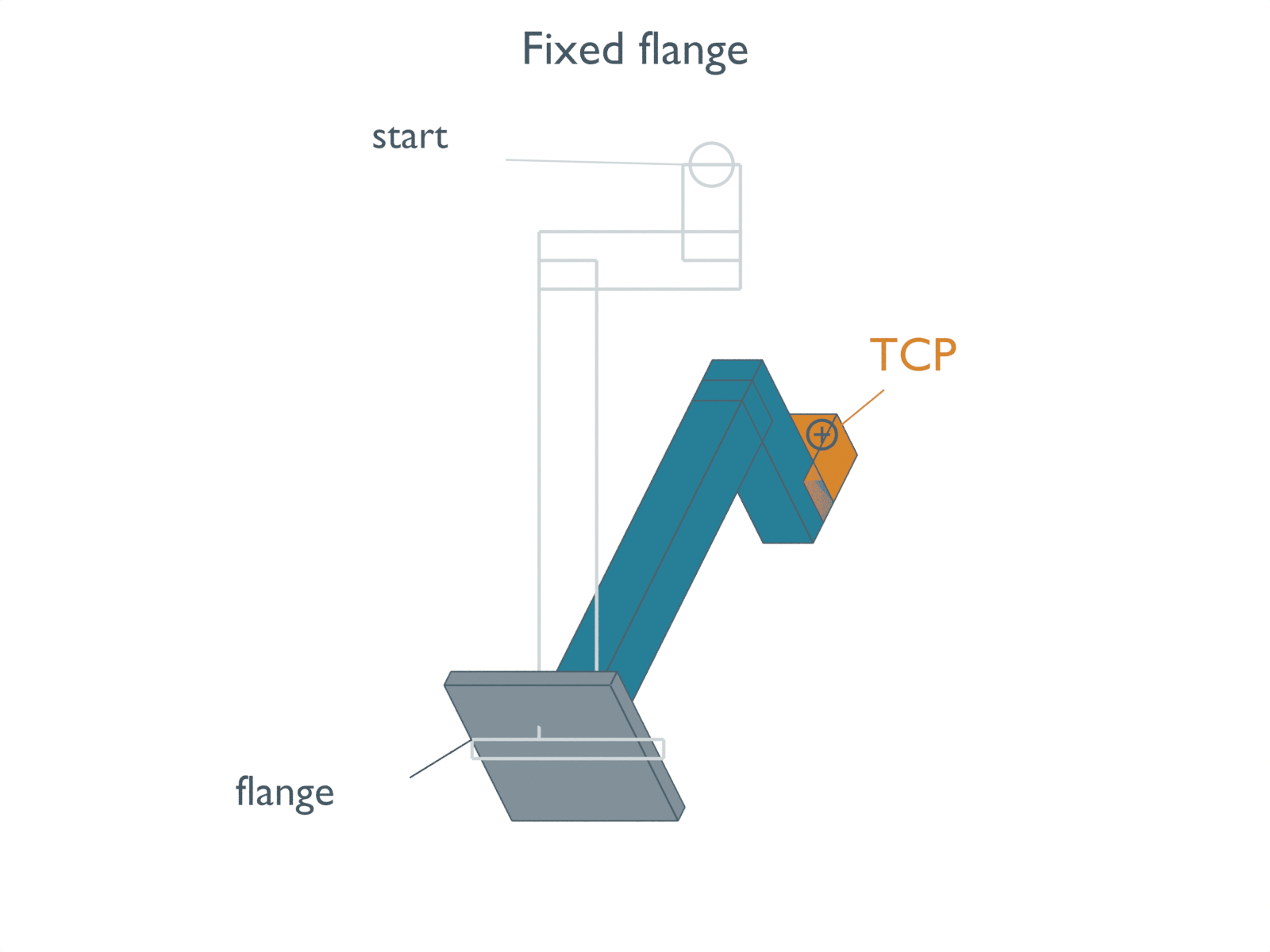
Place a synthetic flange at (400, 100, 300) mm in an arbitrary study frame. Give its rigid tool a tip offset of (30, 0, 120) mm in the flange frame. With the initial frames aligned, the tip is at (430, 100, 420) mm.
Apply a 45° rotation about Y followed by a 60° rotation about Z, about the named fixed study axes using column vectors. The order is part of the requested orientation. These elementary angles are not a robot controller’s rotation-vector input fields.
Holding the flange at its starting coordinates puts the tip at approximately (453.0, 191.9, 363.6) mm. Its 3D displacement from the starting point is 110.2 mm. The rigid offset has kept its length; its direction in the study frame has changed.
To keep the original tip position instead, the flange finishes at approximately (377.0, 8.1, 356.4) mm. The final tool orientation is the same. The chosen fixed point changes the required translation.
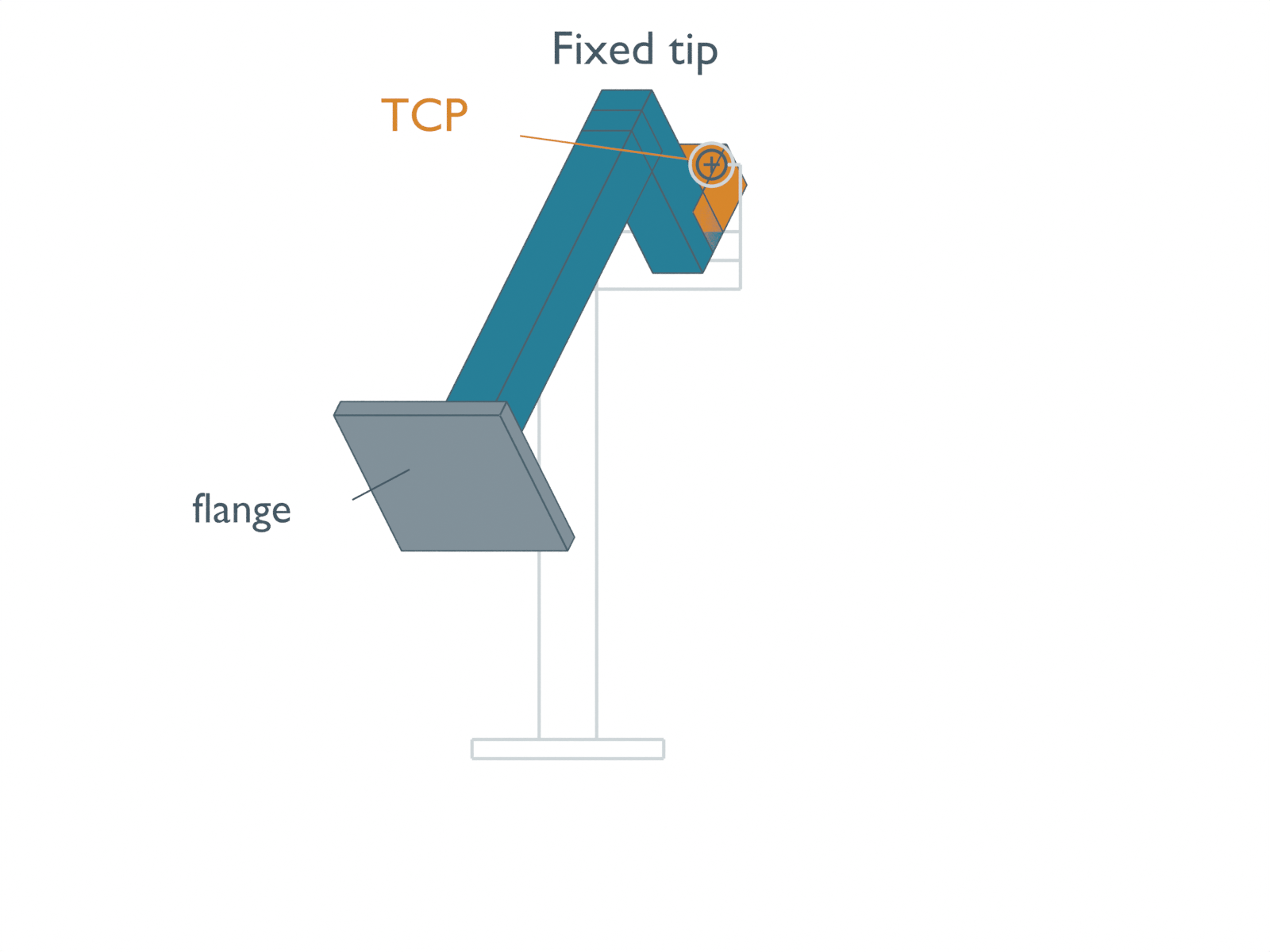
The compensation follows the rigid transform. If R maps flange-local vectors into the study frame, d is the local tip offset and p is the flange position, the tip is p + R d. To hold it at a chosen position c, use p = c − R d. Both vectors in that subtraction must be expressed in the same frame.
Subtracting the unrotated d would return the original flange position here, leaving the 110.2 mm tip displacement. Rotating the whole world position p+d creates another motion: rotation about the study origin rather than about the flange origin.
One fixed point still leaves a moving tool
Here fixed tip means fixed position, not a fixed complete TCP pose. The example’s local TCP axes are aligned with the flange axes. Their orientation in the study frame therefore changes as the tool turns, even when their origin stays at c.
An AI-operated Blender 5.2.2 LTS study on October 5, 2026 retained 61 prescribed poses per case, 122 actual evaluated poses. The finite tool has four boxes: flange plate, stem, elbow and tip. An independent audit checked every world-space corner, edge topology, frame markers and rigid distances, and derived the TCP from the tip mesh’s end-face center. Actual readback reproduced the stated endpoint positions to the displayed 0.1 mm precision and retained the compensated target position within numerical tolerance. That tolerance is a software geometry check, not physical positioning accuracy.
Keeping one face-center point fixed does not freeze the rest of those boxes. A model of clearance around the tool needs its full changing envelope; this study does not solve collision clearance or whether an arm can reach the prescribed poses.
There are useful exceptions to the usual offset motion. A zero offset needs no translation compensation. An offset lying on the axis of a pure rotation also stays in place: (0, 0, 120) mm remains fixed under pure Z rotation about the flange. These boundary cases were included in the independent CPU checks.
Reversing the stated Y-then-Z rotations changes the final fixed-flange tip by about 79.1 mm. Neither order is inherently invalid; switching them changes the requested orientation. Degrees also need conversion before Python’s trigonometric functions use these values.
The following executed standard-library Python reproduces the synthetic endpoints. It contains no robot commands.
from math import radians, sin, cos, sqrt

flange = (400.0, 100.0, 300.0)  # study-frame mm
offset = (30.0, 0.0, 120.0)     # flange-frame mm
pitch, yaw = map(radians, (45.0, 60.0))

def rotate_y_then_z(v):
    x, y, z = v
    x, z = cos(pitch)*x + sin(pitch)*z, -sin(pitch)*x + cos(pitch)*z
    return (cos(yaw)*x - sin(yaw)*y, sin(yaw)*x + cos(yaw)*y, z)

target = tuple(a+b for a, b in zip(flange, offset))
rotated_offset = rotate_y_then_z(offset)
tip_at_fixed_flange = tuple(a+b for a, b in zip(flange, rotated_offset))
flange_for_fixed_tip = tuple(a-b for a, b in zip(target, rotated_offset))
reconstructed_tip = tuple(a+b for a, b in zip(flange_for_fixed_tip, rotated_offset))
assert max(abs(a-b) for a, b in zip(reconstructed_tip, target)) < 1e-10
drift = sqrt(sum((a-b)**2 for a, b in zip(tip_at_fixed_flange, target)))
print("Fixed flange -> tip:", tuple(round(x, 3) for x in tip_at_fixed_flange))
print("Fixed tip -> flange:", tuple(round(x, 3) for x in flange_for_fixed_tip))
print(f"Fixed-flange tip displacement: {drift:.3f} mm")
The native scene stores constant holds at the sampled poses. No physical duration is assigned, and between-frame playback is not a continuous controller trajectory. A fixed target in this model establishes neither TCP calibration nor hardware repeatability, feasible arm motion, contact force or safety.
For a transform model, specify the point to preserve, the offset’s frame and the rotation order before choosing the translation. The existing coordinate-frame and TF2 guide explains the separate problem of frame identity, direction, time and transform ownership. No physical tool or robot was tested here.