For the 70mm slice reference in this Blender model, the rear clamp station preserves 24mm of pad width on the retained side without extra intersections between the guillotine and clamp assemblies. Moving the clamp forward leaves the same 70mm reference but reduces each retained pad width to 7mm, below the chosen 16mm requirement. It also creates seven unwanted solid intersections. Matching the slice length alone would miss both failures.
These results come from Physical AI Lab’s AI-operated static geometry experiment in Blender 5.2.2 LTS. The bale is an intact rigid box, and the blade marks a proposed cut station. No rubber was cut or compressed. The 16mm requirement is an authored geometric condition for this comparison, not a machine specification or a demonstrated workholding limit.
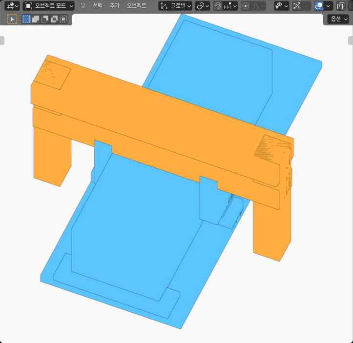
Change the cut station without tying it to the clamp
The industrial motivation comes from EDS Robotics’ AutoBale description, checked on October 11, 2026. It describes a conveyor and guillotine process that weighs, cuts, and sizes a bale according to a mixer formula. That process raises a useful layout question: when the requested portion changes, where can the cut reference sit while leaving enough of the upstream face for the clamp?
The dimensions here are independently authored examples. They are not EDS product CAD, and the vendor description does not establish this model’s pad-width requirement or blade clearance.
In the model’s design coordinates, the bale runs along X from −80mm to +40mm. Its width is 40mm and its height is 30mm. A blade median at X = +10mm leaves a 30mm downstream length reference; a median at X = −30mm leaves 70mm. The median lies halfway between the blade’s two opposing thickness faces. It defines a reference plane through the intact bale, rather than a simulated separation surface.
The clamp has its own station: a rear center at X = −55mm or a forward center at X = −25mm. Each cut station is compared with both clamp stations.
The first functional core contains the fixed base, raiser, and bale, plus a five-member clamp subgroup: a crossbridge, two legs, and two pads. Only the clamp subgroup changes station. The second core contains two columns, a bridge, a carrier, and the blade; those five members share a station. Moving the entire first core would also move the bale and erase the relative change this comparison needs to measure.
Measure the pad face that stays upstream
Each pad has a 24mm length along X. Its inward face projects onto the bale side over a 24mm vertical span. That full face can look suitable even when much of its length lies downstream of the proposed cut.
For this comparison, the retained side means X less than or equal to the blade median. The useful projected region is the intersection of three finite regions: the pad’s inward face, the bale’s opposing side face, and that upstream domain. The bale remains intact in the scene; the domain is a measurement rule, not a removed mesh.
At the rear station, each pad spans X = −67mm to −43mm. Both cut medians sit downstream of that span, so the entire 24mm pad width remains inside the retained domain.
At the forward station, the pad spans −37mm to −13mm. With the short-slice median at +10mm, its full width still lies upstream. With the long-slice median at −30mm, only the span from −37mm to −30mm remains: 7mm. The height stays 24mm, but height cannot repair the missing width under the chosen condition.
This is why a pad center or the unclipped pad dimension is insufficient. The same distinction between a coordinate and a finite span appears in our linear-guide carriage travel comparison. Here, the limiting boundary is the proposed cut plane rather than the end of a rail.
The rear station preserves the longer reference
The measured dimensions below are rounded to 0.01mm. “Extra intersections” excludes the deliberately modeled blade–bale crossing and counts positive-volume overlaps between the guillotine core and clamp members.
| Static configuration | Downstream length reference | Retained width of each pad | Extra intersections | Chosen geometry conditions |
|---|---|---|---|---|
| Short slice, rear clamp | 30.00mm | 24.00mm | 0 | Met |
| Long slice, rear clamp | 70.00mm | 24.00mm | 0 | Met |
| Long slice, forward clamp | 70.00mm | 7.00mm | 7 | Not met |
| Short slice, forward clamp | 30.00mm | 24.00mm | 0 | Met |
The short-slice forward configuration matters because it separates the two station choices. The forward clamp is not intrinsically unsuitable in this model. It becomes unsuitable with the upstream cut median used for the longer slice. Likewise, the longer reference does not require accepting the reduced pad width: the rear-clamp configuration retains all 24mm.
The practical candidate is therefore the long-slice rear station. It meets the two chosen static conditions without changing the requested length reference. That conclusion applies to these dimensions and these configurations, not to a general rule that a rear clamp is always preferable.
Clearing the cut plane does not clear the carrier
The long-slice forward configuration has two kinds of interference. The carrier intersects both clamp pads. The blade intersects the crossbridge, both legs, and both pads. These are seven distinct component pairs, and every one counts as an unwanted overlap.
The carrier extends 7mm along X on each side of the blade median. A check that considers only the thin blade, or only the retained pad width, can therefore miss another finite body occupying the same region. Resolving the 7mm width shortfall would not automatically resolve the carrier intersections; the complete component geometry needs another check after any redesign.
The blade also intersects the intact bale in every configuration. That crossing is intentional because the blade is the cut-location reference. It does not show that the blade traveled through rubber, separated a portion, or completed a cut. The exception belongs only to the blade–bale pair. Extending it to other blade intersections would conceal the clamp conflicts.
Our selective pallet engagement study explores a related mistake: a useful relation with the intended workpiece can coexist with interference elsewhere. In this bale model, preserving the requested downstream length is the useful relation; clearing the surrounding clamp is a separate condition.
Check finite surfaces before accepting a station
To apply this comparison to another layout, begin with the actual finite bale ends, opposing pad faces, and blade thickness faces. Define which side of the median is retained before measuring overlap. Otherwise, a full pad face can silently substitute for the smaller region the decision actually concerns.
Then clip both pad projections against the retained domain and check their widths separately. Keep the complete blade carrier, legs, and crossbridge in the interference calculation. A center point or a bounding-box overlap is not enough to establish the relation between finite surfaces.
For this experiment, the measurements used evaluated vertices and native triangles from Blender. The finite face projections were partitioned using those triangles, and the whole projected region was checked rather than a few selected points. Distance and intersection results used conservative numerical bounds around the captured surfaces. The compared retained face regions were geometrically compatible within an 8µm reconstruction comparison band; that numerical statement does not prove exact physical contact or a loaded contact area.
Choose a station only after the retained face condition and the other component relations agree. If a numerical interval leaves a relation unresolved, keep that result unresolved rather than rounding it into acceptance.
A length reference cannot establish the dose
The 70mm reference says where a downstream portion would end in the authored geometry. It does not establish that portion’s mass. No density distribution, weighing system, material variation, or mixer-formula accuracy was measured. The intact box also contains no rubber compression, adhesion, relaxation, or response to a blade.
Similarly, 24mm of projected pad width does not establish gripping force, friction, stability, or retention during cutting. The chosen 16mm threshold helps compare layouts; a physical workholding requirement would need its own evidence. Positive geometric connections inside the configured cores establish union connectivity in the model, while the pad–bale side-face relation does not become a force-bearing joint simply because its projection overlaps.
For the longer reference in this model, select the rear clamp configuration as the candidate for further engineering. Keep the 70mm length, preserve the retained 24mm pad width, and verify the full carrier and clamp together after any dimensional change. Blade travel, actual cutting, discharge, dose acceptance, and equipment operation remain separate questions that these static configurations have not tested.