Three feet can remain over a usable sample surface while a separate analysis footprint crosses an excluded region. That is the result we obtained when we moved a sample in Blender and left the analysis head at its original pose. Checking the feet alone would have missed the footprint overlap.
In this AI-assisted virtual assembly study, we built a connected sample carrier and a connected head, compared four static arrangements, and measured their actual Blender geometry. An 8 mm sample translation moved roughly half of a 4 × 4 mm reference footprint over the excluded region. Adding a 12° sample rotation changed the overlap to about 8.36 mm². Restoring the full head pose relative to the sample returned the complete footprint to the modeled usable top surface.
The model is deliberately generic. Its dimensions, excluded rectangle and head geometry are ours. We did not run an optical emission spectrometer, a vision system, a robot or a contact simulation. The purpose is to understand a placement check before building those systems: recover the relative pose, then evaluate every relevant finite area.
Why sample position is more than a center point
Optical emission spectroscopy, or OES, is the application context for this exercise. HERZOG describes optional SteelLab vision for choosing a spark location around surface defects and compensating for sample displacement and rotation during placement. That is a supplier description, checked on October 11, 2026, rather than a performance result from our experiment. HERZOG SteelLab product documentation.
A placement problem has several geometries. There is the sample’s outer boundary, an area that should be excluded, the head’s reference footprint, and the areas associated with its feet. A center point does not describe those areas. Nor does a successful check on one area establish the relation of another area to the sample.
We represented the excluded region with an 8 × 6 mm rectangle in the sample’s own coordinates. It is a geometric reference, not a photographed or measured material defect. The head carries a 4 × 4 mm reference column and three larger feet. The column is a convenient closed mesh whose bottom face defines a footprint; it does not represent a real spark volume or an installed probe.
Using a finite rectangle also makes the failure observable in area terms. A point near a boundary can be hard to interpret: which side counts, and how much uncertainty is acceptable? Here the translated footprint crossed the boundary with a substantial positive overlap. We could quantify the overlap without turning numerical precision into a claim about laboratory tolerance.
The two assemblies we actually built
We used Blender 5.2.2 LTS with coordinates in metres and describe the dimensions below in millimetres. The sample coordinate origin lies at the carrier’s plan centre, with Z increasing upward. Four closed coupon pieces form a 50 × 40 mm top at Z = 10 mm, surrounding the central excluded rectangle. A lower base joins those pieces into one connected carrier.
| Component | Authored geometry in its own assembly coordinates |
|---|---|
| Carrier base | X from −30 to 30 mm; Y from −25 to 25 mm; Z from 0 to 6 mm |
| Left and right coupon pieces | X from −25 to −4 mm and from 4 to 25 mm; Y from −20 to 20 mm; Z from 5 to 10 mm |
| Lower and upper coupon pieces | X from −4 to 4 mm; Y from −20 to −3 mm and from 3 to 20 mm; Z from 5 to 10 mm |
| Head plate | X from −15 to 15 mm; Y from −14 to 14 mm; Z from 7 to 13 mm |
| Three head feet | Each 6 × 6 × 8 mm, centred in XY at (−8, −8), (8, −8) and (0, 8) mm; bottom at local Z = 0 |
| Footprint reference column | 4 × 4 × 8 mm, centred in XY at (0, 0); bottom at local Z = 0 |
The four coupon pieces overlap the base by 1 mm. Each foot and the reference column overlap the head plate by 1 mm. These positive connections matter: moving the head means moving the complete assembly, including all three feet and the footprint reference. We did not move the reference column independently to make the result look correct.
The central rectangle has a base underneath it at Z = 6 mm. That lower floor is not part of the usable coupon top at Z = 10 mm. Treating any mesh beneath a projected point as a valid top surface would therefore answer a different question.
We placed the head’s lowest faces at Z = 12 mm, leaving a prescribed 2 mm stand-off above the coupon top. Thus, “over the surface” means a projection onto the sample plane. It does not mean contact, mechanical support or successful analysis. The two cores remain separated in all four states.
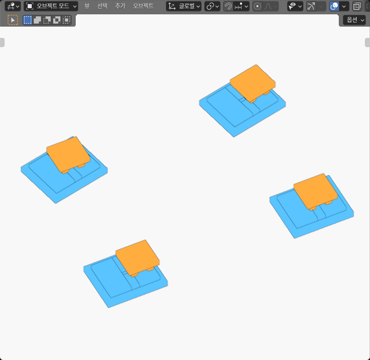
What changed across the four states
The nominal head origin is 12 mm along the sample’s X axis from the sample origin. Its yaw matches the sample’s yaw. This places the reference footprint away from the central excluded region.
For the second state, we translated the sample by +8 mm in world X and left the head unchanged. The head origin consequently lies only 4 mm along X in the translated sample’s frame. Its 4 mm-wide footprint crosses the excluded rectangle’s X = 4 mm edge. All three foot projections still fit within the usable coupon-top union.
The third state retains that translation and rotates the sample by +12° around Z. The unchanged head now has a −12° yaw relative to the sample. Both the footprint position and its orientation in sample coordinates have changed. An axis-aligned rectangle in world coordinates is no longer axis-aligned in the sample frame.
For the fourth state, we authored the head position and orientation to recover the nominal relation: its origin is again 12 mm along sample X, and its yaw matches the sample. This is a prescribed static transform. We did not estimate the pose from an image or execute a robot correction.
| State | Head yaw relative to sample | Reference footprint over excluded region | Each of the three 36 mm² foot projections |
|---|---|---|---|
| Nominal | 0° | 0 mm² | Fully over usable coupon top |
| Sample translated +8 mm; head unchanged | 0° | About 8.00 mm² | Fully over usable coupon top |
| Sample translated +8 mm and rotated +12°; head unchanged | −12° | About 8.36 mm² | Fully over usable coupon top |
| Full relative-pose correction | 0° | 0 mm² | Fully over usable coupon top |
The reference footprint has an area of approximately 16 mm². Its covered usable area fell to about 8.00 mm² after translation and 7.64 mm² after translation plus rotation. It returned to the full 16 mm² in the corrected state. Small deviations from nominal dimensions in Blender’s stored coordinates were included in the calculations; the table rounds those measurements for readability.
The useful observation is the disagreement between the two checks. All three feet passed the projected usable-area check in every state. The separate reference footprint did not. This model therefore provides a concrete counterexample to using foot coverage as a substitute for footprint coverage.
How we measured an opaque model
We kept the complete solid meshes intact. No cutaway or transparent view was used to reveal the central region. The four arrangements contain 40 closed meshes, and we read their actual world-space vertices and faces rather than assuming the requested dimensions were exactly what Blender stored.
For each arrangement, we recovered a sample frame from the actual coupon-top geometry. We removed the arrangement’s display offset, transformed the head’s bottom-face corners into that sample frame, and evaluated the resulting finite polygons. The head position and yaw were checked as part of the same transformation.
The usable surface is the union of four coupon-top rectangles. We calculated each projected footprint’s area within that union and its overlap with the excluded rectangle. We also checked whether any part escaped the outer coupon boundary. This prevents the base under the central opening, or an infinite extrapolation of one coupon face, from being counted as usable surface.
We independently recalculated the areas from the captured world-space coordinates and compared them with the geometry reader’s bounded calculations. Repeated full geometry reads and an additional rigid coordinate transformation provided checks against dependence on the displayed arrangement or a preferred world axis. Those checks support the reported static geometry; they do not validate a physical OES instrument.
The opaque image is an overview of the assemblies. Some lower faces are occluded by the head plate. We rely on the mesh measurements for those hidden areas, not on how much of a foot can be seen in the screenshot.
Carrying the result into a placement workflow
The transform order matters. Suppose the sample has a rotation R and translation t in the world frame. If the desired head-origin offset is 12 mm along sample X, rotate that offset with the sample before adding the sample translation. The desired head orientation must follow the sample orientation as well. Adding 12 mm along world X would preserve the wrong relation after sample rotation.
A practical geometry check can proceed in this order:
- Define the sample’s usable finite top region and every excluded region in sample coordinates.
- Recover or prescribe the complete sample pose and the complete head pose in a common frame.
- Transform the footprint and all relevant foot faces into sample coordinates.
- Check each complete projected area against the usable union, exclusions and outer boundary.
- Evaluate height, contact and application-specific acceptance through their own appropriate models or measurements.
The first four steps explain this Blender study. The fifth was outside it. A real system needs its actual sample shape, surface condition, instrument requirements and pose uncertainty. Our numerical bounds are calculation safeguards, not allowable mechanical positioning errors.
This is closely related to our dual-pickup head study, where a common rigid head pose had to satisfy more than one interface. Here, keeping the head rigid was only the starting point: each of its finite projected regions still needed its own check. Our slide-gate aperture experiment addresses the complementary area question—how much finite opening remains—rather than sample/head placement.
What this experiment leaves open
The corrected state restores coverage in this authored model. It does not establish that a vision system can find the correct pose, that a robot can reach it, or that an instrument would accept the sample. We tested four static arrangements, not a continuous approach path or an optimization over all possible placements.
There is also no conclusion here about support force, spark behaviour, chemical accuracy, surface preparation, robot calibration or production throughput. The excluded rectangle is an authored constraint, and the reference column’s geometry is not a manufacturer’s head design. A different footprint, exclusion shape or uncertainty margin can change the result.
What the actual Blender measurements do establish is narrower and useful: three fully covered foot projections did not establish full coverage of the separate reference footprint. Recovering the sample/head relation restored that footprint in the tested state. If a placement validator currently reports only a centre point or the feet, the next useful addition is a finite-area check in the sample’s own frame.