A rigid position adjustment can align a misplaced beam. It cannot remove a mismatch in the beam’s own shape. In this Blender experiment, aligning both ends of a bowed member left a 4.00 mm gap at its middle interface. Aligning the middle instead pushed both ends into the receiving seats. A third prescribed position shared the residual between the three interfaces, without closing them together.
The useful check was the relationship between all three joint faces. Their projected overlap stayed approximately 480.00 mm² in every state, including the unsuccessful ones. Overlap alone therefore gave the wrong answer to the question I had defined: do all three complete corresponding faces close together?
This is Physical AI Lab’s AI-assisted virtual assembly study. I constructed and inspected the geometry through Blender MCP, then checked the captured coordinates independently. The member is a deliberately simplified, stepped proxy for shape variation. I did not scan reclaimed timber, operate a robot or test a physical joint.
Why I tested three interfaces rather than one beam origin
The motivation came from KIT’s ReFrame project description. It describes adjustments during pick-and-place for slight deformations that scanning may not fully capture. That suggests a useful assembly question: when is a placement adjustment sufficient, and when do the interfaces themselves disagree? I checked the page on October 9, 2026; its displayed last-change date was November 3, 2025. My dimensions and experiment are independently authored, rather than KIT’s geometry or operating procedure.
I separated two kinds of information. A pose describes where a rigid part is and how it is oriented. Shape describes relationships inside that part. Moving the whole part changes its pose while preserving distances between its features. If three required interfaces have incompatible internal distances, improving the object’s placement cannot make their exact correspondence appear.
That distinction matters before choosing a remedy. A different grasp reference, a corrected coordinate transform or a better pose estimate can address placement. Re-machining a joint, allowing a shim or accounting for deformation changes the assembly problem. Those choices need different evidence. This experiment identifies a geometric disagreement; it does not select a repair for real timber.
The two connected cores and reproducible geometry
Each state contains two functional cores: a blue receiving frame and an orange incoming member. The receiver has one base and three attached seats. The incoming member has three overlapping beam segments and three attached pads. These closed boxes form connected unions; they are not ten unrelated samples. The overlapping segments approximate one fixed rigid member and carry no material stiffness model.
I used millimetres for the dimensions below, while the Blender coordinates were expressed in metres. X runs along the beam, Y across its width and Z upward. The receiver’s three seat-top faces lie at Z = 6 mm. Each registered seat and pad face measures 20 × 24 mm. Their corresponding station centres lie at X = −60, 0 and +60 mm.
| Closed member | X bounds, mm | Y bounds, mm | Z bounds before whole-member adjustment, mm |
|---|---|---|---|
| Receiver base | −80 to 80 | −15 to 15 | −8 to 0 |
| Receiver left / middle / right seats | −70 to −50 / −10 to 10 / 50 to 70 | −12 to 12 | −1 to 6 |
| Incoming left / middle / right beam segments | −70 to −15 / −20 to 20 / 15 to 70 | −10 to 10 | 9 to 25; bowed middle: 13 to 29 |
| Incoming left / middle / right pads | −70 to −50 / −10 to 10 / 50 to 70 | −12 to 12 | 6 to 10; bowed middle: 10 to 14 |
For the straight member, every segment and pad uses the unmodified Z range. For the bowed proxy, only the middle segment and its attached pad have the listed 4 mm higher authored bounds. The end segments overlap the middle segment in X, and each pad overlaps its own segment in Z. The receiver seats likewise overlap the base. I checked those connections in the actual closed geometry.
I created four separate static assemblies, without deforming a member between them. Their display origins were (0, 0), (240, 0), (0, 100) and (240, 100) mm in the XY plane. Those translations separate the examples on screen and are removed when comparing local assembly measurements. The bowed examples use the same internal shape, with only a whole-member Z translation changed.
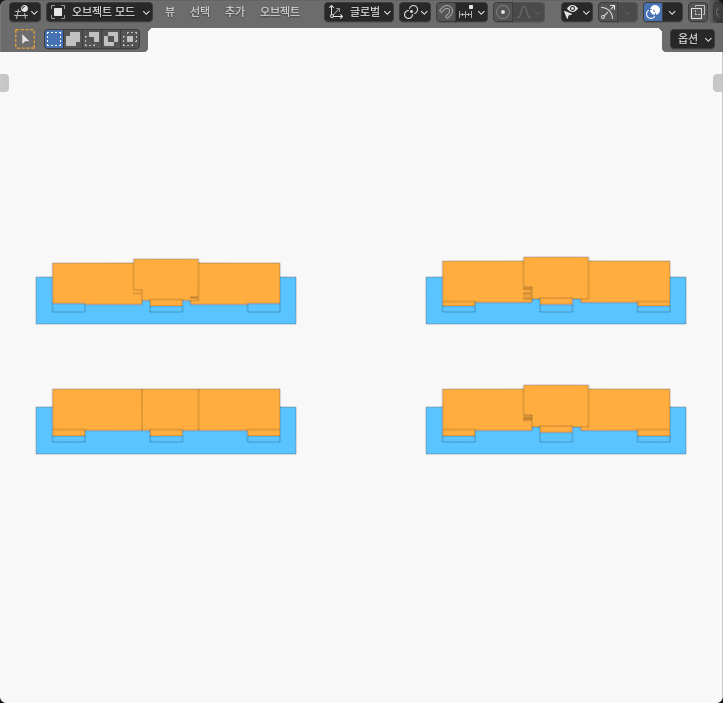
What changed when I moved the complete bowed member
I defined registered closure as agreement of all four corresponding corners of a complete seat-top and pad-bottom face, together with opposed outward normals. All three face pairs must meet that requirement. This is stricter than some projected overlap, a shared centre in one view or a possible point contact.
A positive signed normal gap means the incoming pad is above its seat. A negative value means its registered bottom face is below the seat’s top plane. I separately checked finite solid intersections, so a negative plane relation was not used as a substitute for a material-overlap check.
| Static state | Whole incoming Z shift, mm | Measured left / middle / right gaps, mm | All three registered faces match? |
|---|---|---|---|
| Straight reference | 0 | 0.00 / 0.00 / 0.00 | Yes, within the numerical comparison band |
| Bowed, ends aligned | 0 | 0.00 / +4.00 / 0.00 | No; the middle remains separated |
| Bowed, middle aligned | −4 | −4.00 / approximately 0.00 / −4.00 | No; both end pads intersect their seats |
| Bowed, prescribed balanced position | −2 | −2.00 / +2.00 / −2.00 | No; end intersections and a middle gap remain |
The middle-fit state also produced intersections between the receiving end seats and the outer beam bodies. Checking only the three pad interfaces would have missed those additional conflicts. I examined every receiver-member/incoming-member solid pair: 4 × 6 combinations in each state. The middle-fit state had four strict intersecting pairs; the balanced state had two. The straight reference and end-fit state had no strict interior intersections established by this check.
Projected face overlap was approximately 480.00 mm² at each station in all four states. Moving the member along Z preserved its XY footprint. Even an interface with a 4 mm gap therefore kept the same projected area. This is why a top-view silhouette or an overlap score cannot serve as the full assembly acceptance test here.
I used a 4 μm coordinate correspondence gate and an 8 μm comparison band for the numerical checks, with outward reporting intervals. These are arithmetic verification settings, not fabrication tolerances. The tiny middle-fit residual around zero was retained in the calculation and rounded for the table. A result within the comparison band does not establish a loaded, fastened or structurally adequate contact.
The distance check that separates pose error from shape mismatch
The receiving face centres are collinear: adjacent stations are 60.00 mm apart, and the two end centres are 120.00 mm apart. The bowed member’s middle face centre is 4 mm above its end face centres. Its adjacent centre distances are consequently about 60.13319 mm, while its end-to-end distance remains 120.00 mm.
The actual captured geometry reproduced this pattern. Each bowed adjacent distance exceeded its receiving counterpart by approximately 0.1331855 mm. That excess remained when I moved the whole member down 4 mm or 2 mm. Translation changed the face gaps but preserved the internal centre-distance disagreement.
A rigid transformation preserves pairwise distances. Different distances between corresponding, labelled interface centres therefore provide a necessary obstruction to exact simultaneous centre mapping. Complete face correspondence would require that centre mapping too, so this also rules out exact full closure under the stated rigid correspondence. The result is not a search over every practical joint design or permitted allowance.
The following conceptual check illustrates the idea. It is not the validator used for the recorded Blender experiment and does not inspect complete polygons, normals or finite solid intersections.
from math import dist

def corresponding_distance_residuals(receiver_centres, member_centres):
    pairs = ((0, 1), (1, 2), (0, 2))
    return [
        dist(member_centres[i], member_centres[j])
        - dist(receiver_centres[i], receiver_centres[j])
        for i, j in pairs
    ]
For an application, start with a declared correspondence: which measured joint face must match which receiver? Then compare distances between features before asking a pose optimizer to resolve all interfaces. Inspect every complete required face after placing the part, and check the surrounding solid bodies as well. A solver reporting a successful pose needs an assembly acceptance rule that matches the intended joint.
For a complementary example of reference calibration, see our dual-pickup-head common-pose experiment. The question here concerns internal shape compatibility across three interfaces. A corrected common reference does not change the bowed member’s distances.
What this virtual experiment establishes, and what remains open
I constructed 40 closed mesh members across four assemblies and inspected 320 captured WORLD vertices and 480 native triangles. The checks included three complete reads, a separate representative state and an additional proper cyclic axis permutation followed by restoration. An independently written calculation used the complete captured WORLD geometry and agreed on the gaps, finite overlaps, connections, distance differences and strict intersection pairs. The largest correspondence error against the authored coordinate recipe was approximately 13.11 nm.
The straight reference met the declared three-interface numerical closure rule. None of the bowed placements did. The −2 mm position reduced the largest measured normal residual from about 4 mm to about 2 mm, but I prescribed that position in advance. I did not establish it as a globally optimal rigid fit, and it still contains material intersections.
The distance obstruction applies to exact mapping of these registered features under a rigid transformation. It does not rule out partial face overlap, an accepted gap, changed joint geometry, compliance or deliberate deformation. Each would require a different acceptance rule and further checks. A stepped rigid proxy also cannot supply timber properties, moisture effects, fastening behaviour or structural capacity.
The practical lesson is to make the acceptance question explicit before interpreting a placement result. Here, “the two ends align” and “the middle aligns” were locally correct observations. Neither answered whether the complete member could close all three registered interfaces. For a real reclaimed part, the next inputs would be measured joint surfaces, a defined allowance and an appropriate mechanical assessment. This Blender study supplies a reproducible geometric example of the distinction, with no physical assembly or load-test claim.