Robot actuators convert stored energy into controlled rotary or linear motion. Electric motors dominate many industrial and mobile robots, but hydraulic, pneumatic, screw, belt, cable and compliant mechanisms remain useful where force density, environment, motion, interaction or infrastructure favors them.
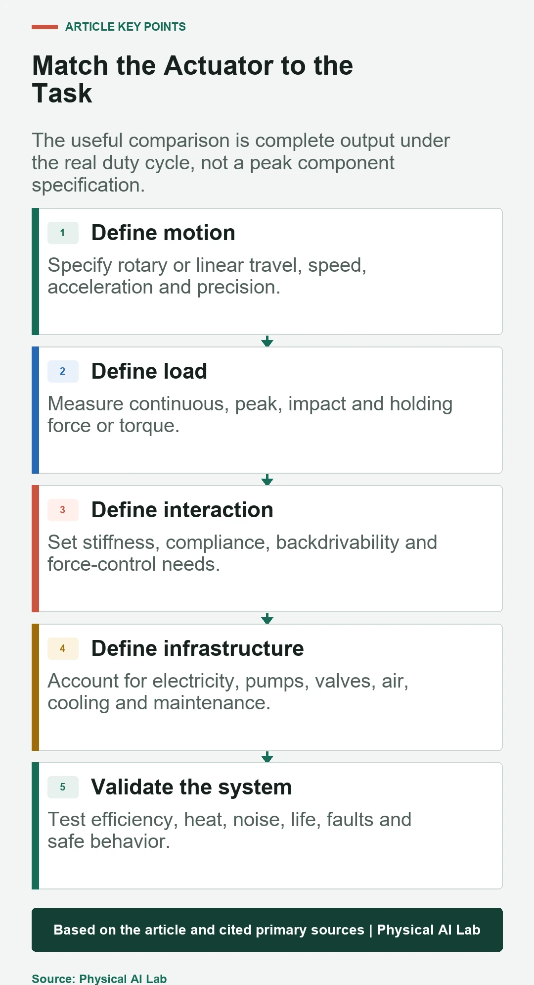
Actuator type should be selected from the task outward. Define continuous and peak force or torque, speed, travel, precision, duty cycle, impacts, stiffness, backdrivability, energy source and safe behavior. Comparing isolated peak numbers hides the mass, heat and maintenance of the complete system.
This guide provides the taxonomy. Use the robot actuator structure, reducer comparison and frameless motor guide for deeper electric-joint design.
Start with rotary or linear output
Rotary actuators produce angular motion around a joint axis. Linear actuators produce force along a stroke and can drive prismatic joints directly or rotate a linkage. Mechanism geometry can transform motion, torque, speed and stiffness across the range.
Specify output coordinates before choosing technology. Include travel, velocity, acceleration, continuous and peak load, holding condition and available space. A compact motor may require a bulky transmission, while a cylinder may need pumps, valves or compressed air elsewhere.
Electric rotary actuators offer controllable distributed motion
Brushless motors with reducers are common because electrical power and digital control can be distributed across many joints. Direct-drive and quasi-direct-drive systems reduce ratio for better transparency and bandwidth but require more motor torque and thermal capacity.
Kollmorgen publishes a compact rotary actuator example combining motor and joint packaging. Product examples illustrate architecture, not a universal choice; compare complete output, drive, feedback, cooling and bearings.
Electric linear actuators convert rotation or use direct linear motors
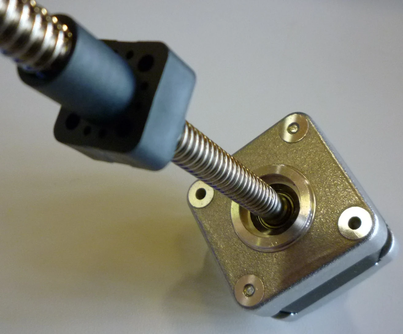
Lead screws and ball screws convert motor rotation into linear motion. Belts and racks provide other speed, stroke and force tradeoffs. Direct linear motors eliminate mechanical conversion but require a guide, feedback and a magnetic track or reaction structure.
Screws can provide precision and large force but introduce critical speed, lubrication, backlash, wear and possible backdriving questions. End stops, anti-rotation guides and brakes may be necessary. Compare efficiency in both driving and holding states.

Hydraulic actuators deliver high force through fluid pressure
Hydraulic cylinders and rotary actuators can produce high force from compact moving elements. Pumps, reservoirs, valves, hoses, filtration, cooling and leak management form the rest of the system. Fluid compressibility and line dynamics affect control.
Hydraulics can suit heavy machines and high-force dynamic robots where infrastructure is acceptable. Evaluate total system mass, noise, efficiency, maintenance, contamination, temperature and failure containment rather than cylinder force alone.
| Actuator family | Typical advantage | System burden | Best comparison metric |
|---|---|---|---|
| Electric rotary | Distributed precise control | Heat and transmission | Joint output per complete mass |
| Electric linear | Direct prismatic motion | Guides, screw or track | Force-speed-stroke envelope |
| Hydraulic | High force density | Pump, fluid and maintenance | System output and efficiency |
| Pneumatic | Simple rapid motion | Air supply and compressibility | Cycle result and air use |
| Compliant | Impact and force interaction | Deflection and control | Task force and bandwidth |
Pneumatic actuators provide simple rapid motion
Pneumatic cylinders and rotary actuators use compressed air and valves. They can be lightweight at the moving point and tolerate some harsh environments. Compressibility, friction and supply variation make precise force and position control more challenging.
Air preparation, compressors, reservoirs, valves, exhaust noise and leakage determine energy and maintenance. Pneumatics often fit repeated end-to-end moves, gripping and compliant fixtures. Servo-pneumatic control is possible but should be evaluated as a complete loop.
Compliant actuators shape interaction mechanically
A series elastic actuator places a compliant element in the load path and estimates force from deflection. The classic series elastic actuator paper explains how deliberate compliance can support force control and shock tolerance.
Compliance stores energy and reduces effective stiffness, but it also adds deflection and limits force-control bandwidth. Variable-stiffness mechanisms add adjustment at the cost of complexity. Passive compliance should be chosen for a task, not treated as an automatic safety guarantee.
Cable, belt and remote-drive systems redistribute mass
Cables, tendons and belts can place motors away from distal joints, reducing moving limb mass. Routing can enable compact hands or arms and introduce useful compliance. Tension, friction, stretch, wear, pulleys and service access become central design issues.
Remote actuation couples joints through the routing structure and complicates calibration. Measure motion and force at the output. Design tensioning and replacement procedures, and verify behavior after cycles and temperature changes.
Energy infrastructure changes the apparent winner
Electric systems need batteries or power supplies, drives and cooling. Hydraulic systems need pressure generation and fluid management. Pneumatics need compressed air and valves. A tethered factory robot and a battery-powered humanoid face very different infrastructure constraints.
Calculate energy from source to verified task output, including idle and holding periods. Regeneration, leakage, throttling, pump operating points and compressor efficiency can change results. Include thermal management and peak-power storage.
| Requirement | Question | Measurement | Failure if ignored |
|---|---|---|---|
| Continuous output | Can heat be rejected? | Temperature over duty cycle | Derating or damage |
| Interaction | How stiff and backdrivable? | Force-motion response | Poor contact control |
| Infrastructure | What supports the actuator? | Source-to-output energy | Hidden mass and cost |
| Maintenance | What wears or leaks? | Service time and interval | Low availability |
| Fault behavior | What happens without power? | Injected-fault response | Drop or uncontrolled motion |
Safe behavior depends on mechanics and control
Power loss can release a load, hold it through friction, or trap stored pressure and elastic energy. Brakes, counterbalance devices, relief valves and mechanical stops manage these states. Their behavior must be included in the hazard analysis.
Force limits and software stops do not replace structural protection. Test sensor faults, stuck valves, drive faults, burst lines, brake release and regeneration. Recovery procedures should account for payload, robot pose and maintenance personnel.
Selection ends with a task-level prototype test
Create a scorecard from the actual task: output envelope, precision, compliance, efficiency, mass, volume, noise, environment, maintenance, safety and cost. Apply consistent system boundaries so remote pumps or compressors are not omitted from one technology.
Build a representative axis and run trajectories, impacts, holding periods, environmental exposure and faults. Log input energy, output work, temperature, position, force and interventions. The best actuator type is the one that meets the complete robot requirement with verifiable margin.
- Define motion and load at the output.
- Include the complete energy infrastructure.
- Compare continuous behavior, not peak output alone.
- Evaluate compliance, faults and maintenance.
- Validate a representative axis under the real duty cycle.
Frequently asked questions
What are the main robot actuator types?
Common families include electric rotary and linear actuators, hydraulic and pneumatic systems, and mechanisms using deliberate compliance, cables or remote drives.
Why are electric actuators common in robots?
They integrate well with batteries, electronics and digital control, and can be distributed across many axes. Heat and transmission design still limit performance.
When are hydraulic actuators useful?
They are useful when high force and robust dynamic output justify pumps, fluid, cooling, noise and maintenance infrastructure.
What is a series elastic actuator?
It places a known compliant element in the force path. Measuring its deflection can estimate force and improve impact tolerance, with tradeoffs in deflection and bandwidth.
How should actuator types be compared fairly?
Compare verified task output using the same duty cycle and system boundary, including energy source, drive, transmission, cooling, sensing, maintenance and fault behavior.
Actuator Selection Note
Actuator performance depends on the complete mechanism, energy source, controller and environment. Verify current component ratings and standards, then test representative hardware under task, life and fault conditions.