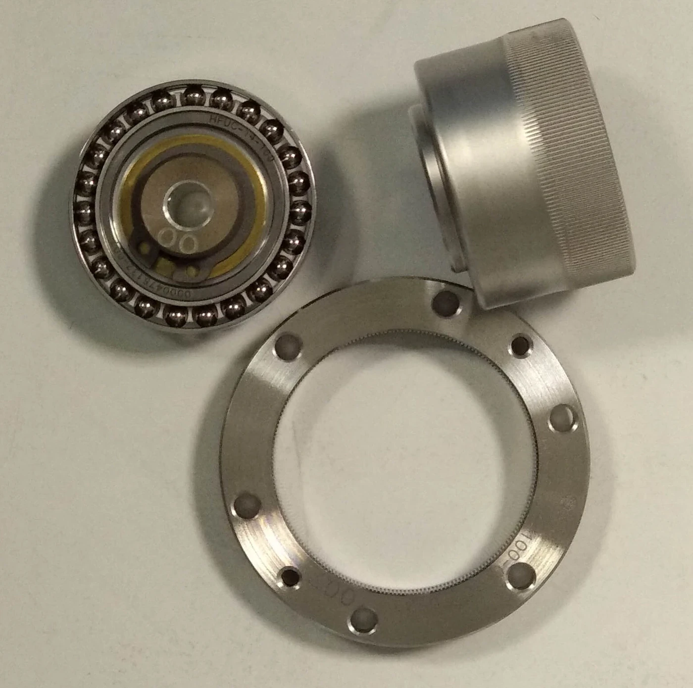
A harmonic drive, also called a strain-wave reducer, creates a large speed reduction in a compact coaxial mechanism. It does so with three central parts: an elliptical wave generator, a thin flexible spline and a rigid circular spline with a slightly different number of teeth.
The mechanism is elegant, but its robot performance is not explained by ratio alone. Elastic deformation, tooth loading, bearings, lubrication, housing stiffness, installation and duty cycle determine backlash, lost motion, efficiency, heat, overload behavior and life.
This principle guide extends the robot reducer comparison and actuator structure guide. Verify current supplier drawings, limits and installation instructions for any selected component.
The wave generator creates a rotating ellipse
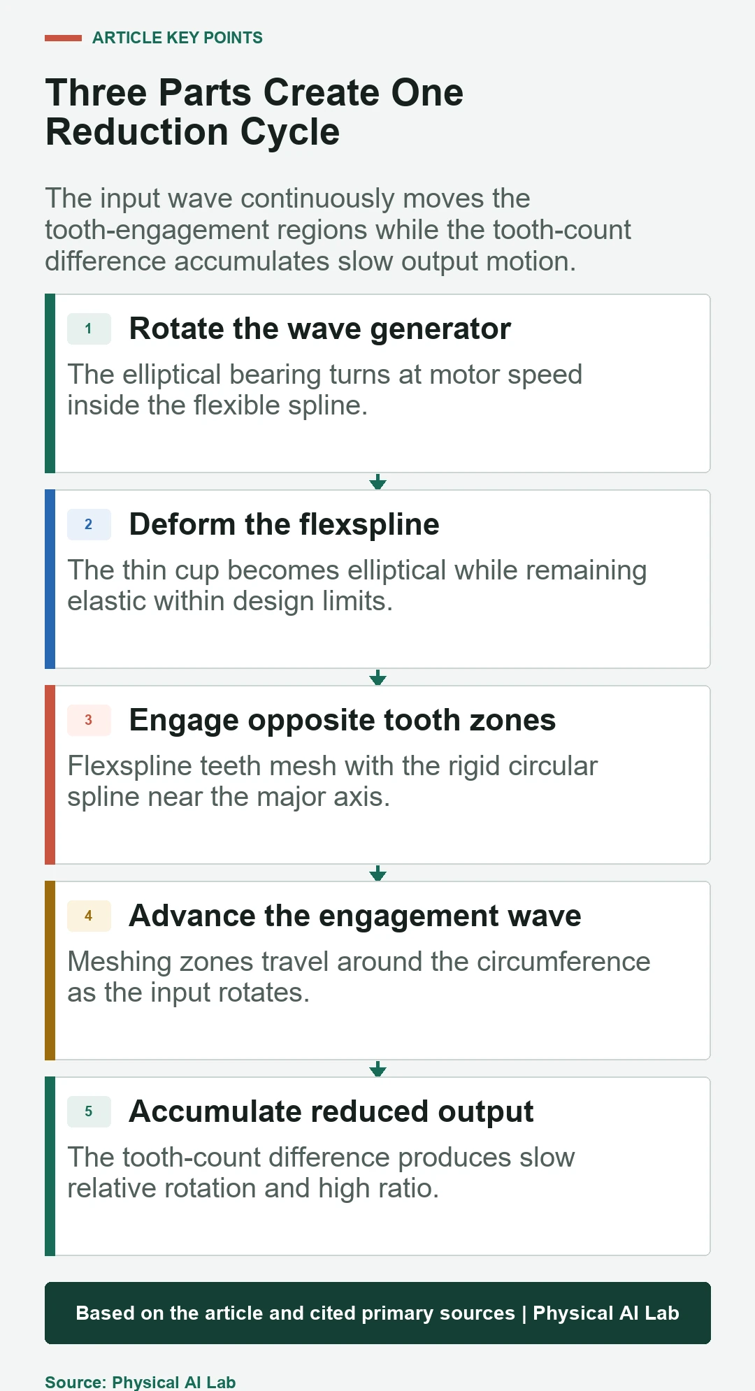
The official operating-principle reference shows an elliptical plug surrounded by a flexible bearing. Motor input rotates this wave generator inside the flexspline, imposing controlled elastic deformation.
The major axis pushes opposite regions of flexspline teeth outward into the circular spline. The minor-axis regions remain disengaged. The bearing must support continuous cyclic deformation while preserving geometry and lubricant conditions.
The flexspline is both gear and elastic element
The flexspline is commonly a thin cup with external teeth near its open end. Its wall bends into an ellipse and returns as the wave passes, while its closed end transfers slow output motion or reacts torque depending on the arrangement.
This repeated elastic cycle makes material, wall geometry, heat treatment and manufacturing defects important to fatigue life. The part should remain within the intended elastic range; overload and installation distortion can shorten life even when the joint still turns.

The circular spline provides the rigid tooth reference
The circular spline is a rigid ring with internal teeth. It normally has slightly more teeth than the flexspline. The difference is small in count but produces a large relative reduction over a complete wave-generator revolution.
Housing and mounting must preserve circularity and alignment. Distortion can change tooth contact, torque distribution, noise and life. The rigid label describes the design role, not immunity to poor installation.
| Part | Mechanical role | Critical behavior | Integration risk |
|---|---|---|---|
| Wave generator | High-speed input and deformation | Elliptical rotation | Bearing and lubrication |
| Flexspline | Elastic geared output | Cyclic strain | Fatigue and overload |
| Circular spline | Rigid tooth reference | Distributed mesh | Housing distortion |
| Output support | Carries external joint loads | Alignment and stiffness | Bearing moment capacity |
A tooth-count difference creates the reduction ratio
As the wave generator turns, the two tooth-engagement regions travel around the circumference. Because the flexspline has fewer teeth, it shifts by the tooth-count difference relative to the circular spline after one full input revolution.
The sign and exact ratio depend on which member is fixed, driven and used as output. Engineers should use the supplier’s defined kinematic arrangement rather than copying a memorized formula without its reference frames.
Many teeth share load at the engagement regions
Multiple simultaneous tooth contacts distribute torque and enable compact output. Load is not uniform across every engaged tooth, and the distribution changes with deformation, manufacturing error, torque and support stiffness.
The mechanism’s high ratio and low backlash are valuable in robot joints, but contact stress and flexspline strain still require rated limits. Peak torque, repeated peak torque, momentary overload and collision torque are different conditions.
Low backlash does not mean infinite stiffness
Preloaded elastic engagement can minimize conventional gear clearance. The joint still deflects because of flexspline compliance, tooth deformation, bearings, housing and fasteners. Reversals can show hysteresis and lost motion even without obvious free play.
Measure output angle against torque in both directions. Use the intended mounting and temperature and separate repeatability, transmission error, torsional stiffness and lost motion. These quantities affect position and force control differently.
Efficiency changes across speed, torque and temperature
Bearing motion, tooth contact, flexing and lubricant shear create loss. Light-load efficiency can be dominated by friction, while high load raises contact and elastic loss. Temperature changes lubricant behavior and component dimensions.
Map mechanical input and output power over the task envelope. Include no-load current and joint thermal rise. A single efficiency value cannot predict battery energy or continuous robot torque.
| Test | Primary measurement | What it exposes | Design use |
|---|---|---|---|
| Torque-angle sweep | Hysteresis and stiffness | Lost motion and compliance | Control model |
| Efficiency map | Input and output power | Friction and heat | Motor and cooling |
| Transmission-error sweep | Output angle versus ideal | Periodic motion error | Calibration |
| Impact test | Post-event geometry and noise | Overload damage | Protection |
| Life spectrum | Performance drift over cycles | Fatigue and wear | Maintenance interval |
Installation is part of the mechanism
Component-set reducers rely on customer housing, bearings and fasteners. Runout, concentricity, flange flatness and clamping can alter performance. Integrated units reduce some work but still need correct interfaces and external load management.
Follow the current installation procedure for tolerances, lubricant, bolt sequence and allowable loads. Measure the assembled joint instead of assuming catalog values survive a different structure.
Control must account for elastic transmission behavior
A motor encoder observes the input while the load moves after an elastic, frictional reducer. Torque estimated from motor current includes friction and model uncertainty. Output sensing can improve observability of joint angle and deflection.
Log motor and output position, current, torque and temperature on a common clock. Tune controllers for the changing load and temperature range, and avoid aggressive compensation that fits one bench condition but destabilizes another.
Validation connects the principle to a real robot joint
Run no-load, loaded, reversal, thermal, impact and life tests with the intended motor, drive, feedback and housing. Inspect multiple samples and track efficiency, stiffness, transmission error, noise and calibration drift.
The working principle explains why the reducer can be compact and precise. It does not certify a particular joint. Hardware evidence under representative duty cycles is the final basis for torque, life and control decisions. For a manufacturing example, our analysis of Schaeffler’s formed strain-wave gearbox separates the supplier’s validation claims from the evidence still needed for use in a robot joint.
- Trace input, fixed member and output frames.
- Separate ratio from stiffness and lost motion.
- Map efficiency and temperature across the task.
- Follow installation and external-load limits.
- Validate impact, control and lifetime on the assembled joint.
Frequently asked questions
What are the three main harmonic drive parts?
The wave generator, flexible spline and circular spline form the central strain-wave mechanism.
Why does a harmonic drive have a high ratio?
A small difference in flexspline and circular-spline tooth counts accumulates slow relative motion during one wave-generator revolution.
Does a harmonic drive have zero backlash?
It can have very low conventional backlash, but the installed joint still has elastic deflection, hysteresis and transmission error.
Why can the flexspline fail?
It experiences repeated elastic cycling and tooth load. Overload, distortion, lubrication, manufacturing and duty cycle influence fatigue life.
How should a harmonic drive be tested?
Measure the complete joint for torque-angle behavior, efficiency, transmission error, heat, impacts and life across representative conditions.
Mechanism and Rating Note
Harmonic-drive ratings depend on model, arrangement, mounting, lubrication and duty cycle. Verify current supplier documentation and test the assembled actuator before using catalog values in a robot design.