Robot joint friction is the torque that resists or modifies motion across bearings, seals, gears, flexsplines, cables and lubrication. It changes with direction, speed, temperature, load, dwell and wear. Near zero speed, breakaway and stick-slip behavior make a simple constant-friction assumption especially weak.
Compensation estimates the friction torque and adds a bounded feedforward or observer-based correction before feedback error grows. It can improve low-speed tracking, force transparency and model residuals, but an abrupt or excessive estimate can cause reversal chatter, drift or unsafe contact behavior.
Use this guide with the robot system-identification guide and joint gain-tuning guide. Identify friction separately from cogging, gravity, inertia and transmission hysteresis before changing the controller.
Friction is a family of operating regimes
Static friction is the range of resisting torque before sliding begins. Once motion starts, the Stribeck region can show decreasing friction with increasing very low speed. Coulomb friction is approximately direction-dependent and speed-insensitive over a band, while viscous friction increases with speed. Real joints may also show presliding hysteresis.
These labels are model components, not separate physical parts. Bearings, seals, lubricant and gearing contribute together. Choose the simplest model whose residual and control performance remain acceptable across the intended motion, rather than fitting every textbook term to limited data.

Measure motor and joint torque on a clear path
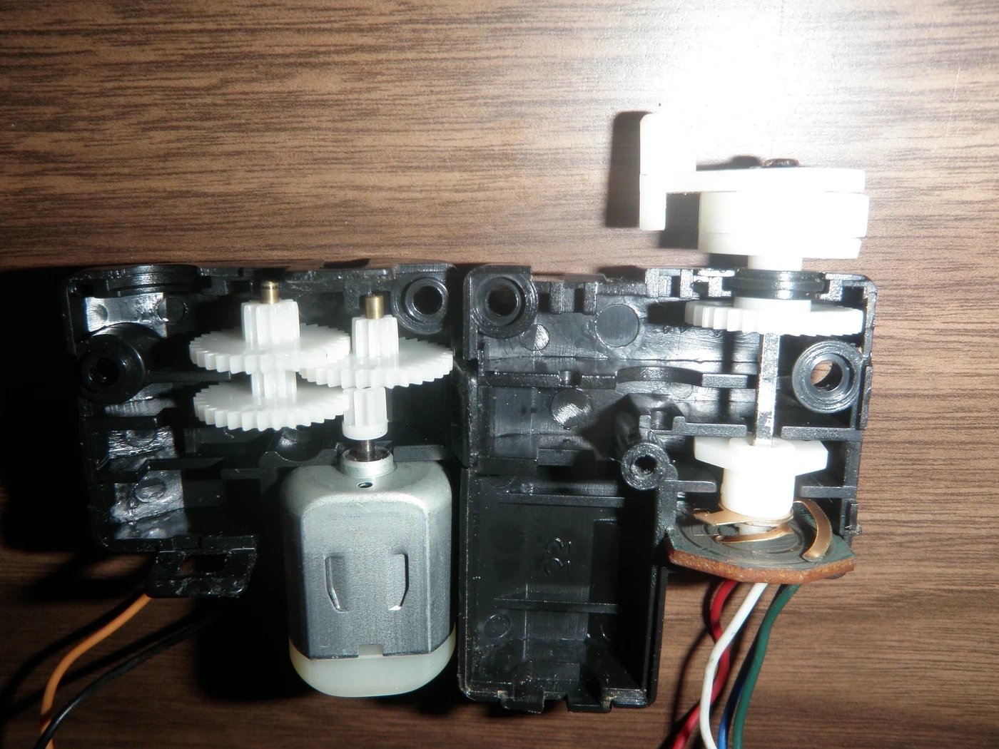
Motor current estimates electromagnetic torque only after current-sensor calibration and torque constant. Gear ratio, efficiency, drive compensation and inner current-loop error separate that estimate from joint output torque. A joint torque sensor or external load cell provides different observability and its own calibration.
Document command and measured variables, units, signs and timestamps. Disable or record existing gravity, friction and disturbance compensation. Otherwise the experiment estimates the combined behavior of the plant and hidden controller instead of the physical loss to be compensated.
| Regime | Typical model term | Main evidence | Risk when wrong |
|---|---|---|---|
| Stiction | Breakaway bound | Slow torque ramp | No motion or jump |
| Stribeck | Low-speed decay | Dense near-zero sweep | Stick-slip |
| Coulomb | Signed constant | Both directions | Bias |
| Viscous | Velocity coefficient | Wider speed sweep | Speed-dependent error |
| Presliding | Hysteresis state | Small reversals | Limit cycle |
Use bidirectional steady-speed sweeps
Move the joint at a series of nearly constant positive and negative speeds while holding pose and load conditions as stable as possible. In steady motion, inertial torque is small; subtract modeled gravity and known external load to estimate the remaining friction and unmodeled effects.
Approach each speed from both directions and repeat after warm-up. A difference between positive and negative curves contains direction asymmetry plus calibration bias. Very slow tests need enough dwell to reach a stable mean but should not average away stick-slip cycles.
Separate friction from gravity and inertia
An incorrect mass, center of gravity or joint zero appears as a pose-dependent torque error. Acceleration adds inertial torque, and cables or neighboring joints can couple forces. Design trajectories that isolate one variable at a time or estimate all selected terms together with an identifiable model.
The system-identification workflow explains held-out validation and residual analysis. Plot the friction estimate versus position, speed, acceleration, direction and temperature. Structure outside the chosen variables means the model is absorbing another effect.
Temperature and load change the curve
Lubricant viscosity and seal behavior change during warm-up. Bearing preload and harmonic-drive contact change with transmitted torque. A curve measured cold and unloaded can overcompensate a warm loaded joint. Log motor, reducer or housing temperature and time since startup.
Build separate parameter sets or a scheduled model only when data support the additional dimensions. Interpolate smoothly and bound extrapolation. State the validated temperature, pose and payload range so the controller does not treat an unmeasured condition as a precise estimate.
| Test variable | Why vary it | Observed signature | Model response |
|---|---|---|---|
| Direction | Expose sign and asymmetry | Positive-negative gap | Separate branches |
| Speed | Separate regimes | Stribeck to viscous curve | Velocity function |
| Temperature | Lubrication change | Warm-up drift | Scheduled parameter |
| Load | Transmission and bearing loss | Torque-dependent offset | Load term |
| Pose | Gravity and cable effects | Position structure | Correct dynamics first |
Feedforward and integral feedback have different roles
Friction feedforward predicts a repeatable torque from desired or measured motion and acts before tracking error. Integral feedback accumulates persistent error and can remove bias without an explicit model, but it reacts later and can wind up at saturation. Neither should be used to hide a wrong sign or unsafe limit.
Desired velocity gives a clean scheduled command but can push through an obstacle or misestimate friction when motion stalls. Measured velocity reflects actual motion but is noisy and ambiguous at zero. Many designs blend signals with state logic and strict torque, rate and workspace limits.
Observers estimate unmodeled disturbance with delay
A disturbance or momentum observer compares measured motion and torque with a dynamics model to estimate external and internal disturbance. Friction, contact, model error and sensor bias can all enter the same residual. The estimate is useful only with known bandwidth and interpretation.
Research on friction observers for flexible-joint robots illustrates methods that use torque measurements without requiring one static curve. Observer filtering adds delay, and aggressive cancellation can reduce robustness. Keep contact detection and friction compensation objectives distinct.
Zero-speed sign changes can create chatter
A pure Coulomb model using an abrupt sign of velocity jumps between positive and negative torque near zero. Encoder noise and quantization then switch the command rapidly. Smooth sign approximations, deadbands, state machines or presliding models can reduce the discontinuity but also leave residual friction.
Test small reversals, holds, micro-motions and contact transitions. Measure current, audible noise, position limit cycle and temperature. Do not tune smoothing only on a large trajectory where zero-speed instability is hidden by continuous motion.
Do not confuse cogging and transmission effects
Cogging repeats with rotor mechanical angle and can exist without current. Friction depends strongly on direction and speed. Backlash and hysteresis create path-dependent lost motion and elastic loops. A single residual trace can contain all three after the reducer maps motor to joint coordinates.
Use the cogging torque comparison and reducer behavior guide to design isolation tests. Compensating friction with an angle table or cogging with a velocity sign term obscures the diagnosis.
Validate improvement and robustness together
Compare tracking error, breakaway delay, low-speed ripple, required feedback effort and energy with compensation disabled and enabled. Use held-out velocities, loads, poses and temperatures. Report percentile and worst behavior around reversals, not only average trajectory error.
Then test saturation, sensor noise, unexpected contact, stalled motion and parameter mismatch. Compensation should remain bounded and should not defeat collision monitoring or make the robot push harder through an obstruction. Reidentify after lubrication, reducer, seal, payload or major thermal changes.
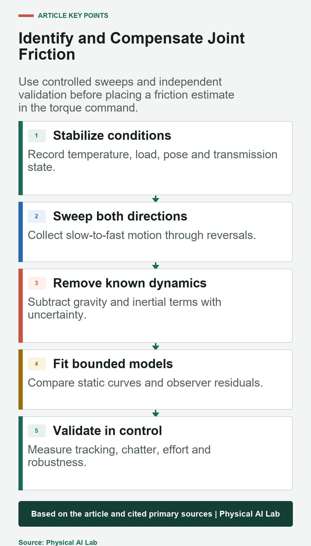
- Stabilize and record temperature and load.
- Sweep speed in both directions.
- Subtract gravity and inertia with uncertainty.
- Bound and smooth any compensation law.
- Validate zero-speed, contact and mismatch behavior.
Frequently asked questions
Is Coulomb friction completely independent of speed?
It is an approximation over a sliding-speed range. Near zero, Stribeck and presliding effects matter, while higher speed can add viscous and thermal dependence.
Can integral gain remove friction?
Integral action can reduce steady error, but it does not identify friction and may wind up or overshoot. Feedforward and integral feedback serve different roles.
Should compensation use desired or measured velocity?
Either can be used with tradeoffs. Desired velocity is clean but may not reflect stalled motion; measured velocity is physical but noisy near zero. Validate the chosen blend.
How is static friction measured?
Apply a controlled, bounded torque ramp or very slow motion in both directions and record breakaway under known load, pose and temperature.
What should improve after compensation?
Held-out low-speed tracking, breakaway delay and feedback effort should improve without added chatter, saturation, contact force or sensitivity to model mismatch.
Friction Compensation Control Boundary
Friction compensation is controller-specific and can reduce robustness when overapplied. Keep torque and motion limits independent and validate across zero speed, load, temperature and contact.