Robot joint thermal management connects electrical and mechanical losses to internal temperatures, cooling paths, output derating and duty-cycle validation. Continuous torque is therefore a system result, not merely a motor or gearbox catalog value.
Copper, inverter, bearing, seal and transmission losses occur in different places and respond differently to speed, load and ambient conditions. Surface temperature may look acceptable while a winding, semiconductor or lubricant approaches its limit.
Use this guide with the joint actuator testing guide and quasi-direct-drive actuator guide. Temperature limits and cooling changes require component data, validated models and qualified electrical and mechanical review.
Every loss source heats a different part of the joint
Motor copper loss rises approximately with current squared, while iron and mechanical losses depend on speed, flux and construction. Inverter switching and conduction, bearing friction, seals and gear meshing add heat outside the winding.
Build a loss budget across representative torque-speed points. Measure electrical input and mechanical output where possible, then reconcile the difference with temperature and component models. A single efficiency number can hide the hotspot that sets the actual limit.

Peak and continuous output follow different thermal clocks
Thermal capacitance lets a cold joint tolerate short peaks before critical parts heat substantially. It does not remove the energy; repeated peaks accumulate until heat rejection balances loss or a limit is reached.
Specify peak duration, repetition, starting temperature and recovery. Define continuous torque under the real ambient, airflow, mounting and speed. A bench rating with a large heat sink may not transfer to an enclosed moving robot joint.
Internal temperatures cannot be inferred from touch
A cool housing does not prove a safe winding or inverter. Thermal resistance and time delay separate internal sources from accessible surfaces. Conversely, a warm housing can indicate that heat is being conducted out effectively.
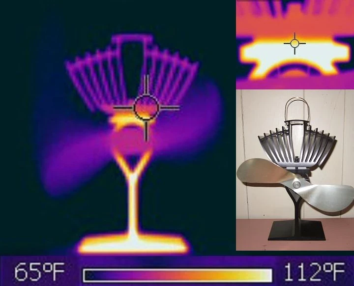
Use embedded sensors where available and estimate inaccessible states with calibrated models. Record sensor location, contact, filtering and lag. Thermal cameras help map surfaces but require emissivity control and cannot see through housings.
| Temperature location | Why it matters | Measurement option | Main limitation |
|---|---|---|---|
| Motor winding | Insulation and torque limit | Embedded sensor or model | Local hotspot |
| Inverter | Semiconductor reliability | Board sensor | Junction estimate |
| Bearing | Lubricant and preload | Nearby sensor | Poor direct access |
| Gearbox | Efficiency and lubricant | Housing and oil estimate | Spatial gradient |
| Housing surface | Heat rejection and touch | Contact or infrared | Emissivity and lag |
A thermal network connects sources, masses and boundaries
A lumped thermal model represents heat capacities and resistances between winding, stator, housing, gearbox, structure and ambient. More detailed finite-element models can study geometry, but both require boundary conditions and measurement.
Identify parameters from controlled experiments at several operating points. Validate heating and cooling transients, not only one steady temperature. Parameter values can change with pose, contact pressure, airflow, lubricant and assembly variation.
The housing is both structure and heat exchanger
Joint housings carry load, locate bearings, protect components and conduct heat into links. Material, wall thickness, contact area and interfaces influence both stiffness and thermal resistance.
Improve flatness, contact pressure and thermal interfaces before adding active cooling. Avoid moving heat into a temperature-sensitive sensor or person-contact surface. Mechanical tolerances and serviceability must remain acceptable.
Passive, forced-air and liquid cooling have different costs
Passive conduction and convection are simple and quiet but depend strongly on area, orientation and ambient air. Forced air adds heat-transfer capacity with fans, ducts, contamination and noise. Liquid cooling offers high heat transport but adds pumps, seals, hoses and leak risk.
Compare cooling by continuous output gained per mass, volume, electrical power and maintenance burden. Include pump or fan failure behavior and condensation risk. Cooling can improve capacity without correcting an inefficient transmission or oversized duty cycle.
| Approach | Strength | Penalty | Validation focus |
|---|---|---|---|
| Passive | Simple and low maintenance | Limited heat flux | Pose and ambient |
| Forced air | Moderate capacity | Fan, dust and noise | Flow loss and failure |
| Liquid | High transport capacity | Leaks, pump and hoses | Pressure and fault containment |
| Structural conduction | Uses robot links | Interface sensitivity | Contact resistance |
| Operational scheduling | No added hardware | May reduce throughput | Task and recovery time |
Derating should be predictive and stable
Thermal derating reduces current, torque, speed or task intensity before a protected component exceeds its limit. A sudden hard cutoff can destabilize a robot or interrupt work in an unsafe state.
NASA’s intelligent actuator control research description illustrates control that accounts for temperature dynamics near actuator limits. Production designs still require component-specific verification, margins and independent protection.
Current-based estimates need measured correction
Current provides a useful estimate of copper heating but misses iron, gearbox, bearing, seal and inverter losses. Motor constants and resistance also change with temperature. A current-only limit may be conservative in one region and unsafe in another.
Fuse current, speed, ambient and measured temperatures in a model with bounded uncertainty. Detect failed or implausible sensors. Preserve a conservative fallback and log why derating occurred so field data can improve calibration.
Pose and workflow change the thermal boundary
A vertical joint may carry gravity torque continuously while another alternates around zero. Adjacent actuators, batteries and electronics warm the structure. Covers, clothing or confined spaces can reduce airflow compared with an open bench.
Test representative poses, payloads, speed profiles, dwell and ambient conditions until steady state or a defined limit. Include restart from a warm condition and back-to-back cycles. Validate the worst credible workload, not only an average trajectory.
Improve losses and heat paths before raising limits
Prioritize the component that controls temperature margin. Reducing current demand, friction, preload or gear loss can improve both efficiency and heat. Better interfaces, spreading area and cooling then move the remaining heat more effectively.
Revalidate torque accuracy, stiffness, sealing, noise and life after thermal changes. Keep a traceable thermal budget and derating map in firmware configuration. The best solution preserves required work while maintaining component limits and predictable recovery.
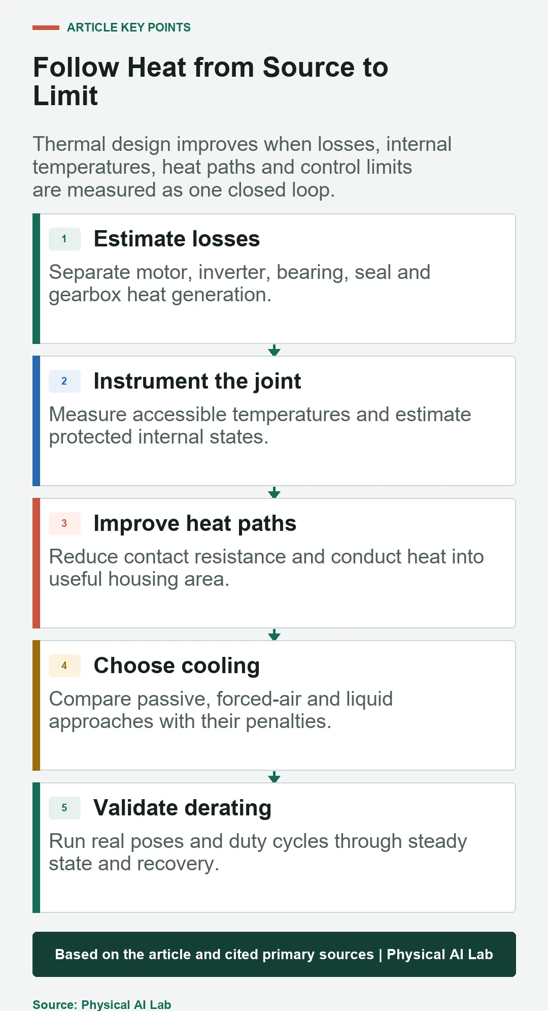
- Map losses across the real torque-speed region.
- Measure surfaces and estimate protected internal states.
- Validate thermal models during heating and cooling.
- Choose cooling with mass and maintenance penalties.
- Test derating under real poses and duty cycles.
Frequently asked questions
Is a cool joint housing proof that internal parts are safe?
No. Internal hotspots can be separated from the housing by thermal resistance and time delay.
Does higher peak torque imply higher continuous torque?
No. Peak output is short-duration capability; continuous output depends on losses, cooling and allowable temperatures.
Will a larger fan solve joint overheating?
Not necessarily. Airflow may not reach the controlling hotspot, and added dust, noise, power and failure modes must be considered.
Where should temperature sensors be placed?
Place them near decision-critical components where feasible, then calibrate models for inaccessible hotspots and record sensor lag.
Can a thermal model control derating without sensors?
A model can estimate states, but it should be validated and corrected with measurements, bounded for uncertainty and backed by conservative protection.
Thermal Safety Note
Thermal limits affect insulation, semiconductors, lubricants, bearings, structures and human contact. Use component-rated limits, validated sensors and models, conservative fault handling and qualified review before changing cooling or derating.