A robot safety-control architecture is the complete functional chain that detects a hazardous condition, decides on a response and brings the physical machine to a defined safe state. Two sensors, a safety PLC or a watchdog timer cannot establish that result in isolation.
The engineer must specify channel independence, diagnostic coverage, response time, final switching, brake and energy behavior, reset and restart. Common-cause and systematic faults matter because they can defeat apparently redundant hardware at the same instant.
This guide is educational and does not establish conformity. Use it with the robot functional-safety guide and the robot risk-assessment guide, then apply current normative standards and qualified validation.
Define the complete safety function before selecting components
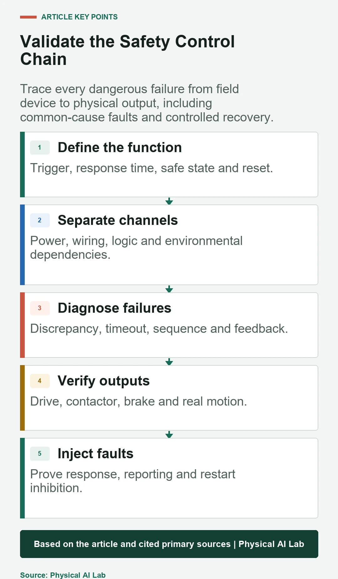
Write the initiating condition, operating modes, required response, maximum response time, final physical state, reset conditions and deliberate restart behavior. Include sensing, input modules, logic, communications, drive safety functions, contactors, brakes, actuators and feedback in one boundary.
Trace which hazardous motion or process energy each function controls. A product certificate supports a subsystem claim only within its stated configuration and conditions; it does not prove the installed application function.
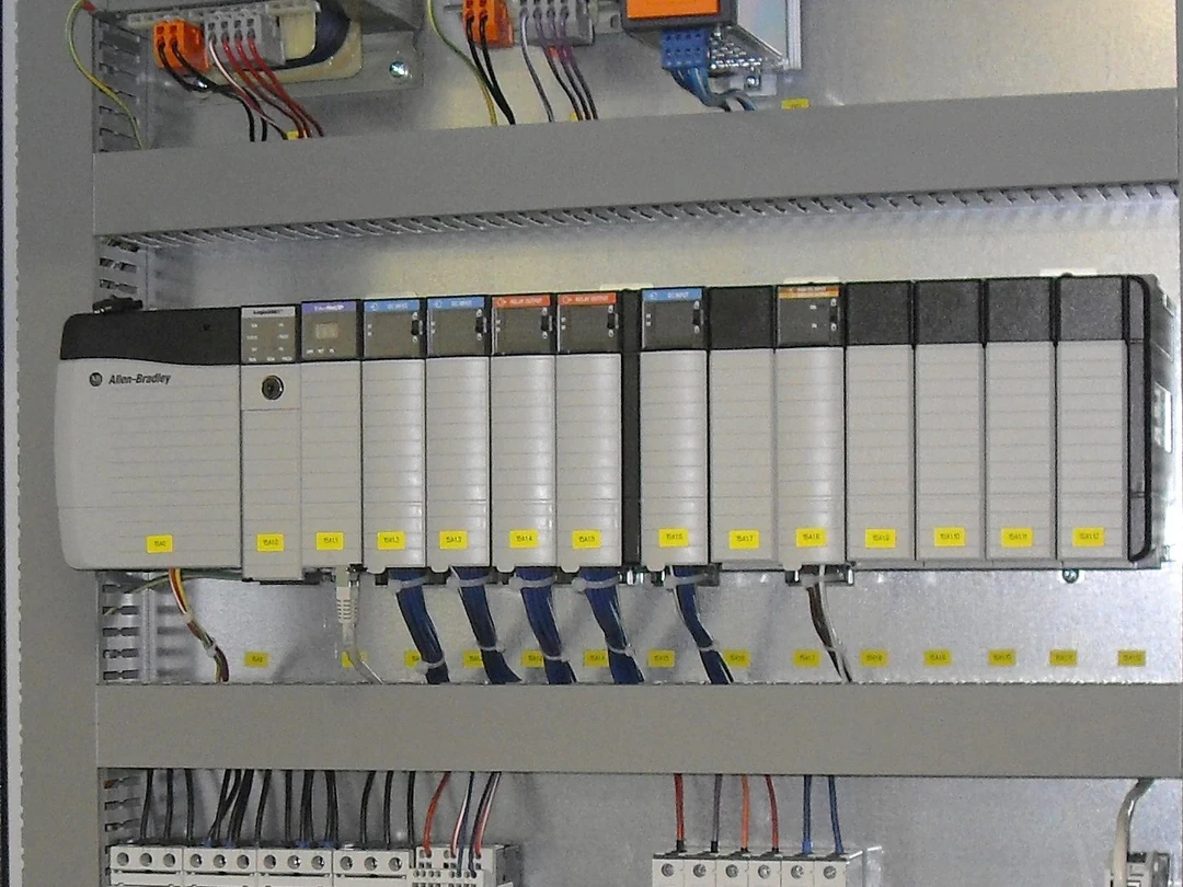

Use dual channels to tolerate and diagnose credible faults
Independent channels can make one open circuit, short, stuck contact or sensor fault visible through disagreement. The design must define where channels begin, where they are compared and how a detected discrepancy changes outputs and restart permission.
Redundancy without diagnostic timing can leave a first fault latent until a second fault occurs. Specify discrepancy windows from real contact and sensor behavior, then verify that a window cannot be stretched merely to suppress nuisance trips.
Control common-cause failure instead of counting channels
Two paths routed through the same cable, supply, connector, cabinet hot spot, software component or coordinate assumption can fail together. Review power transients, contamination, heat, vibration, electromagnetic interference, maintenance errors and shared requirements.
Use justified separation, independent protection, environmental ratings, diversity where appropriate and controlled wiring practices. Record what remains shared so calculations and tests do not silently assume impossible independence.
| Safety-chain element | Credible fault | Diagnostic evidence | Required reaction |
|---|---|---|---|
| Field sensor | Open, short or stuck | Pulse and discrepancy test | Safe state plus fault |
| Logic | Task, memory or program fault | Self-test and cross-check | Disable affected output |
| Communication | Loss, delay or replay | Sequence, integrity and timeout | Defined fallback |
| Final element | Stuck switch or brake failure | EDM and motion feedback | Restart inhibited |
| Shared resource | Power or environment | Independent monitor or analysis | Escalated safe response |
Treat watchdogs as timing monitors with explicit blind spots
A processor watchdog can detect an overrun or stopped task, and a heartbeat can detect a missing peer. Neither necessarily detects a sensor frozen at a plausible value, an incorrect coordinate transform or an algorithm that repeatedly transmits the wrong command on time.
Add reasonableness, freshness, range, cross-channel and physical feedback where the fault model requires them. The ROS 2 real-time control guide explains deadline and jitter measurement, but ordinary real-time monitoring is not automatically a safety function.
Verify message source, sequence, age and integrity
A safety-related communication path must distinguish a current message from a delayed, repeated, inserted or misrouted message. Define identifiers, counters, time or age rules, integrity checks and a bounded reaction to loss or invalid state.
Cybersecurity controls such as authentication and authorization address malicious access, while functional-safety communication mechanisms address defined random and systematic communication failures. Connect the analyses without treating one as a substitute for the other; see the ROS 2 and DDS security guide.
Keep the safety PLC inside its certified application boundary
Check the exact safety PLC, firmware, I/O, function blocks, scan-time assumptions, environmental limits and proof-test conditions. Ordinary variables, online edits, force functions and bypass bits must not undermine safety logic or escape access control.
The official IEC page describes IEC 62061:2021 with Amendment 1:2024 as covering design, integration and validation of safety-related control systems for machinery. Apply its current scope and the chosen architecture through a project-specific functional-safety plan.
Verify the commanded output and the physical result
A logic bit saying that Safe Torque Off was requested does not prove that every drive reacted, a welded contactor opened, a holding brake engaged or hazardous pressure disappeared. Use output readback, external-device monitoring and relevant motion or energy feedback.
Gravity axes require special attention because removing motor torque can permit motion. Link the sequence to the robot joint brake and safe-stop guide and test the actual payload, pose and adverse supply conditions.
Define safe state, reset and restart as separate decisions
A safe state can mean stopped motion, maintained position, vented pressure, isolated process energy or another hazard-specific condition. State what must remain energized to preserve safety and what happens when the preferred controlled stop cannot complete.
Clearing a fault or resetting a safety device should not itself initiate hazardous motion. Specify visibility, presence checks, mode selection and a separate deliberate start, then test loss and restoration of power and communication.
Control systematic faults and configuration drift
Wrong requirements, duplicated software defects, incorrect channel mapping and unreviewed parameter changes can defeat redundancy without any component breaking. Use version control, independent review, restricted changes, reproducible builds and a signed or hashed configuration baseline.
Link every safety requirement to diagrams, program objects, parameters and test cases. Firmware, tool, payload, network, controller or AI-policy changes trigger impact assessment and selective or complete revalidation.
Inject faults through the entire chain
Under an approved safe test plan, simulate an input open circuit, stuck value, cross-short, frozen heartbeat, repeated sequence, processor overrun, output stuck state, welded contactor and feedback mismatch. Observe physical motion and energy, not only an alarm message.
Record detection time, achieved state, diagnostic code, operator information and restart inhibition. A machine that stopped for an accidental reason has not demonstrated the specified fault reaction.
Apply current safety-control standards within scope
The official ISO catalog lists ISO 13849-1:2023 as the published fourth edition for design and integration of safety-related control-system parts. The current published validation edition is ISO 13849-2:2012, while a successor is under development.
Choose applicable editions, required PL or SIL and machine-specific Type-C standards from the legal and project context. Public summaries and component marketing do not replace the normative documents or competent engineering judgment.
Release an auditable safety-control evidence file
Preserve the safety-requirement specification, channel and dependency diagram, failure analysis, calculations, certificates and restrictions, software and configuration versions, fault-injection procedures, timing traces, physical results and residual risks.
Close review with the following checks.
| Acceptance area | Required evidence | Failure pattern | Revalidation trigger |
|---|---|---|---|
| Requirement | Trigger, time and safe state | Vague stop command | Hazard or mode change |
| Architecture | Channels, diagnostics and CCF | Shared hidden dependency | Hardware or wiring change |
| Logic | Reviewed version and parameters | Uncontrolled bypass | Firmware or program change |
| Physical output | Measured motion and energy | Bit-only confirmation | Drive, brake or payload change |
| Fault testing | Injected case and trace | Alarm without safe result | Test method or interface change |
- Define each function from trigger to physical safe state.
- Show channel independence and common-cause controls.
- State what every watchdog can and cannot detect.
- Verify final elements, brakes and residual energy.
- Control reset, restart, bypass and every relevant change.
Frequently asked questions
Do two safety sensors automatically create a dual-channel function?
No. Independence, diagnostics, common-cause controls, logic, outputs and validation must support the complete function.
Can a watchdog detect every software error?
No. It can detect selected timing or liveness failures, but plausible wrong values and flawed requirements need other checks.
Does a safety PLC guarantee a PL or SIL?
No. The exact application architecture, components, program, wiring, calculation and validation must meet the requirement.
Are encrypted messages automatically safety messages?
No. Security protects against selected threats; safety communication also needs bounded detection of loss, delay, replay and misrouting.
Should fault injection damage real hardware?
No. Use approved simulation, test interfaces and manufacturer procedures that expose the failure path without creating uncontrolled danger.
Safety-Control Evidence Boundary
Accept a robot safety-control architecture only when the complete sensing-to-actuation path, diagnostic limits, safe state, reset, restart and fault response are demonstrated for the installed application.