Performance Level and Safety Integrity Level describe the reliability required and achieved by a defined safety-related control function. They are not blanket grades for a robot, a controller or a collaborative workspace. The function must have a named hazardous event, trigger, safe response, timing requirement and reset behavior.
A risk assessment determines the required risk reduction. The chosen functional-safety standard then guides architecture, component reliability, diagnostic coverage, common-cause measures, software and validation. Sensors, logic, communications, drives, brakes and final mechanical behavior all belong to the safety-function chain when they affect the response.
Use this guide with the robot collision-detection guide and robot joint-control commissioning guide. A certified safety PLC or drive can support a claim, but integration and task-specific physical validation remain the responsibility of the machine design.
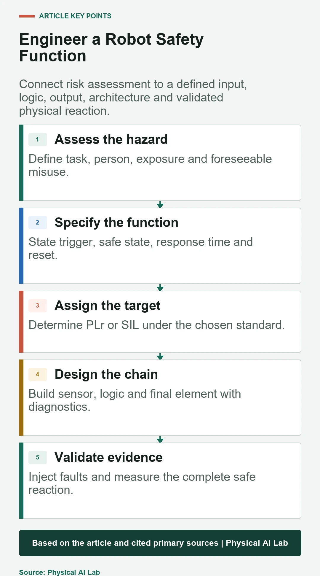
Begin with a hazard and operating situation
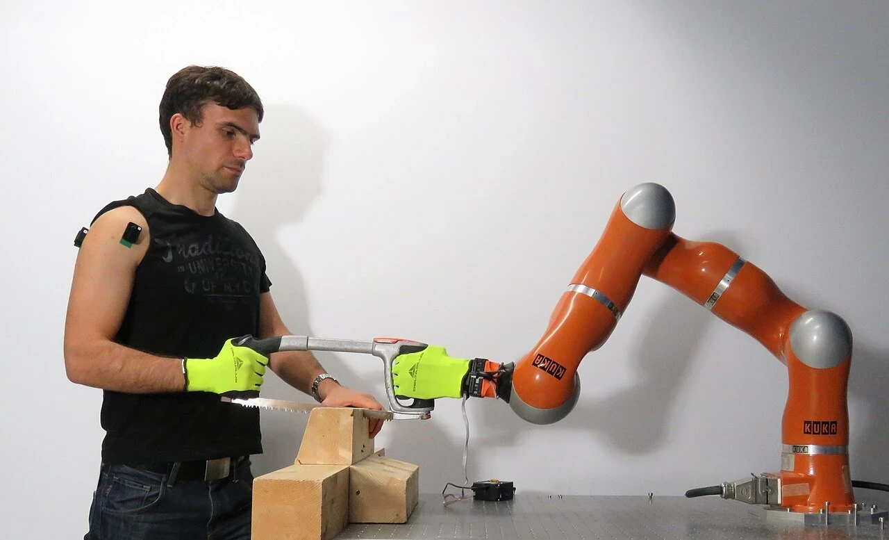
Define the task phase, people who can enter, robot and tool energy, possible contact, trapping, ejection and loss-of-control scenarios. Include setup, teaching, clearing a jam, maintenance and foreseeable misuse rather than assessing only automatic production. The same robot can need different safeguards in different modes.
Estimate severity, exposure and possibility of avoidance using the method required by the applicable machinery framework. Record assumptions about speed, separation, access and supervision. The output is a required risk reduction for each safety function, not a general preference for the highest available category.

Specify the safety function as an input-to-action chain
Write the initiating condition, sensing boundary, logic decision, output action, maximum response time and resulting safe or controlled state. Examples include protective stop when a scanner zone is entered, safe limited speed during teaching or prevention of unexpected restart after a guard opens.
State behavior for power loss, communication loss, diagnostic fault and reset. A safe state is application-specific; removing torque can allow a vertical axis to fall, while holding torque can preserve hazardous energy. Mechanical brakes, gravity and stored pneumatic or elastic energy must be considered with the electrical chain.
| Specification item | Question | Evidence | Common omission |
|---|---|---|---|
| Trigger | What event initiates the function? | Sensor coverage test | Blind zone |
| Logic | What decision is made? | State and fault table | Mode bypass |
| Final element | What removes or limits hazard? | Drive or valve response | Mechanical coasting |
| Timing | How soon must risk be controlled? | Worst-case measurement | Average only |
| Reset | How can operation resume? | Restart interlock test | Automatic restart |
PL and SIL use different calculation frameworks
ISO 13849-1 expresses achieved Performance Level from a through e for safety-related parts of control systems. IEC 62061 uses Safety Integrity Levels for machinery safety-related control systems, generally SIL 1 through SIL 3. Both address high or continuous demand machinery functions, but their terminology and calculation routes are not interchangeable labels.
Do not rank PL e and SIL 3 by name or substitute one value without the permitted mapping and context in the applicable standards. Choose the framework required by the machine, jurisdiction, customer and Type-C product standard. Keep every calculation, subsystem boundary and mission time consistent within that framework.
ISO 13849 combines architecture and reliability evidence
An ISO 13849 analysis considers the designated architecture category, dangerous mean time to failure of channels, average diagnostic coverage, common-cause failure measures and software or systematic requirements. A dual-channel diagram does not automatically achieve a high PL if both channels share a vulnerable power source, sensor principle or software defect.
The current ISO 13849-1:2023 page states that the standard provides a methodology for safety-related control systems but does not select the required PLr for a particular application. That target still comes from the risk assessment and relevant machinery standards.
IEC 62061 structures safety-related control subsystems
IEC 62061 decomposes a safety-related control function into subsystems and subsystem elements, then combines probabilistic and architectural constraints with systematic measures. Interfaces and communication that carry the function require explicit treatment; a reliable logic solver cannot compensate for an unmonitored final element.
The IEC 62061:2021 plus Amendment 1:2024 page describes design, integration and validation requirements for machine safety-related control systems. It also distinguishes functional safety from other machine-level safeguards and security measures, which remain necessary when relevant.
| Evidence area | PL-oriented term | SIL-oriented term | Robot example |
|---|---|---|---|
| Target | PLr | Required SIL | Protective stop |
| Random hardware failure | MTTFd and DCavg | PFH and subsystem data | Scanner to drive |
| Architecture | Category and structure | Architectural constraints | Dual channels |
| Common cause | CCF measures | Dependency control | Shared power or clock |
| Validation | Functional and fault tests | SCS validation | Measured stop response |
PFHd supports a function claim but is not the whole claim
Probability of dangerous failure per hour is calculated across the safety-function chain using component and subsystem data under stated assumptions. Use mission time, duty, diagnostic intervals and environmental limits that match the actual machine. Copying a catalog PFHd for one component as the machine result omits the rest of the path.
Random hardware metrics sit beside systematic capability, software lifecycle, configuration control, installation rules and validation. Track revisions of libraries, parameters and certified drive options. A firmware or wiring change can invalidate evidence even when the product number remains similar.
Certified components do not certify the integration
Safety-rated scanners, PLCs, networks and drives provide safety manuals, limits and reliability data. The integrator must apply them within their assumptions, configure diagnostics, respect proof-test intervals and verify interfaces. A muted scanner, wrong reset circuit or uncontrolled brake can defeat an otherwise qualified chain.
Review independence between channels, routing, power, connectors, environmental exposure and maintenance access. Confirm that non-safety software cannot overwrite protected parameters or bypass the function. Where cybersecurity can affect safety, manage it as a coordinated risk without claiming that one discipline replaces the other.
Validate faults and the resulting physical stop
Inject representative open circuits, shorts, stuck signals, network loss, stale data, disagreement and final-element faults under controlled conditions. Verify detection time, diagnostic reaction, latching and recovery. Tests should prove that a dangerous single fault is controlled as the design claims, not merely that an error code appears.
Measure total response and stopping distance at worst credible speed, payload, pose, temperature and supply condition. Include sensor response, logic scan, communication, drive reaction, brake buildup and mechanical coast. Use the end-to-end timing approach for trace discipline while keeping the safety chain independent of ordinary AI timing.
Collaborative operation is a task-level application
A collaborative-capable robot does not make every application collaborative. End-effector hazards, fixtures, workpiece edges, trapping geometry, transferred energy and human access change the assessment. Speed and separation monitoring, hand guiding, safety-rated monitored stop and power-and-force limiting are different design measures with distinct conditions.
Define transitions between automatic, collaborative, teaching and maintenance modes. Validate zone entry, stop, restart and unexpected-mode requests. Collision detection in a standard controller may improve monitoring but is not automatically a safety function with the required integrity and independence.
Maintain a safety-function evidence file
Link each hazard to its safety function, required PLr or SIL, architecture, subsystem data, calculations, safety requirements specification, software revision and validation cases. Record deviations and residual risks. This traceability is more useful than a single certificate because it shows why each measure exists.
Revalidate after tool, payload, speed, layout, controller, firmware, network or safety-parameter changes. Periodic tests should detect degradation that online diagnostics cannot. Keep measured stopping data and fault-injection logs with the released configuration so later maintenance can confirm the claim still applies.
- Derive targets from task-specific risk assessment.
- Specify trigger, safe state, response time and reset.
- Use one coherent PL or SIL framework.
- Validate component assumptions and integrated faults.
- Measure physical stopping behavior across the envelope.
Frequently asked questions
Is PL e automatically higher than SIL 3?
No. PL and SIL belong to different standards and calculation frameworks. Use the framework and any permitted correspondence defined for the application rather than ranking the labels.
Does a safety PLC automatically provide the required PL or SIL?
No. It contributes qualified logic and data, but sensors, wiring, final elements, common causes, configuration and validation determine the complete function.
Can a collaborative robot operate without guarding?
Only when the task-level risk assessment and validated protective measures support that arrangement. Tools, workpieces and trapping geometry can still require guarding.
Can AI vision be used as a safety sensor?
Only if the complete sensing function is developed and validated to the required safety integrity for its application. Ordinary perception accuracy is not a functional-safety claim.
What document should be created first?
Start with the risk assessment and safety requirements specification linking each hazard to a defined function, target level, timing and safe response.
Functional Safety Application Boundary
PL and SIL claims depend on the applicable standards, jurisdiction, machine task and validated safety-function chain. This guide is technical context, not a conformity assessment or certification.