Robot sensors convert light, distance, motion, joint position, force, pressure and other physical quantities into measurements. Physical AI depends on these streams to estimate the world and the machine itself. A model cannot recover information that the sensor layout never observes, and it should not treat noisy readings as perfect state.
Sensor selection begins with the task. Navigation needs free-space and localization evidence. Manipulation needs object geometry, wrist pose, contact and grip state. Human interaction needs coverage of people and protective devices. The correct suite depends on range, resolution, rate, latency, environment, failure tolerance and cost.
Sensors are the first stage of the Physical AI see-think-act loop. Their outputs become useful only after calibration, synchronization and state estimation connect them to robot decisions. More devices do not guarantee a better state if their frames and timestamps disagree.
RGB cameras capture appearance and semantic cues
RGB cameras record color and texture useful for recognizing objects, reading labels, detecting people and interpreting scenes. Resolution, field of view, exposure, lens distortion and frame rate affect performance. Reflections, glare, darkness, motion blur and occlusion can remove task-critical evidence.
Camera placement should cover the workspace without creating unavoidable blind spots. A fixed camera gives a stable global view, while an eye-in-hand camera obtains close views as the arm moves. Multiple cameras add coverage but increase calibration, synchronization and bandwidth requirements.
Depth cameras estimate three-dimensional structure
Stereo, time-of-flight and structured-light cameras estimate depth using different physical principles. Stereo depends on matching image features, time-of-flight measures returned light timing or phase, and structured light observes a projected pattern. Range, sunlight, reflective surfaces and transparent objects affect them differently.
Depth supports object pose, bin geometry, obstacle distance and grasp planning. Missing or biased depth near edges can produce unsafe collision geometry. Validate the chosen sensor on representative materials, distances and lighting instead of relying only on the nominal range specification.
| Sensor | Measures | Strength | Common limitation |
|---|---|---|---|
| RGB camera | Color image | Semantics and texture | No direct metric depth |
| Stereo depth | Depth from disparity | Passive and texture-rich scenes | Weak on low texture or glare |
| Time of flight | Active range | Direct dense distance | Multipath and sunlight effects |
| Structured light | Projected-pattern depth | Accurate indoor close range | Interference and outdoor limits |
LiDAR measures range across the surrounding scene
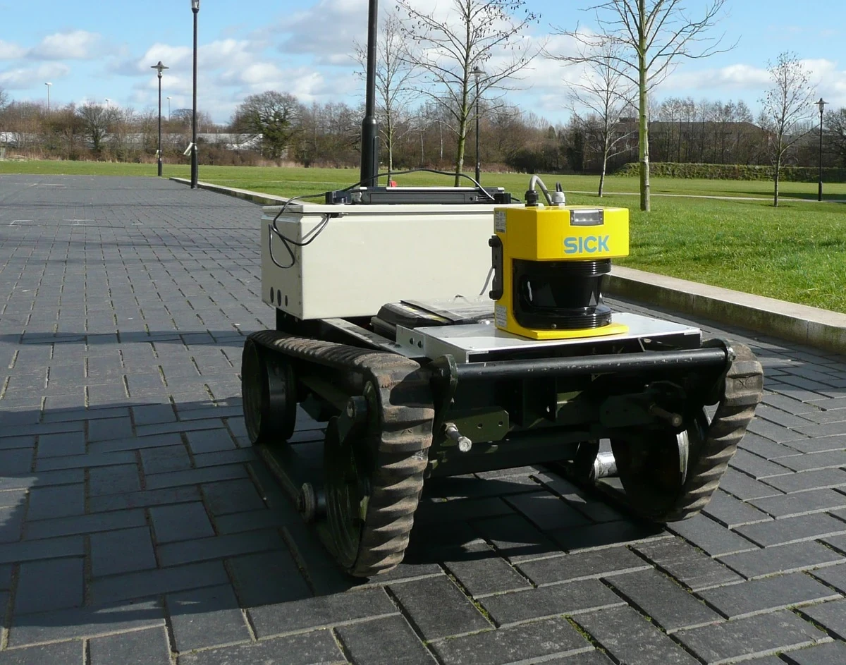
Lidar sends light and measures returns to form ranges or a point cloud. Two-dimensional scanners support planar navigation, while multi-beam and solid-state devices provide richer three-dimensional coverage. Angular resolution, return strength, scan pattern and motion distortion shape the data.
For a mobile robot, lidar can support mapping, localization and obstacle detection even when visual texture is weak. Glass, dark surfaces, weather and limited vertical coverage can still create failures. A low-mounted planar scanner may miss tabletops or overhanging obstacles.


IMUs measure rotation and linear acceleration
An inertial measurement unit commonly combines gyroscopes and accelerometers. It provides high-rate motion evidence between slower camera or lidar updates. Bias and noise accumulate when inertial data is integrated, so another reference is usually needed to limit drift.
Mounting rigidity, axis alignment, vibration and temperature affect the signal. Walking robots also experience impacts that can saturate or disturb readings. Calibration and filtering should match the motion spectrum rather than smoothing away the rapid event that control needs.
Encoders reveal the robot's internal motion
Joint encoders measure motor or joint position, and derived values estimate velocity. Incremental and absolute devices differ in how position is recovered after power-up. Motor-side and output-side encoders observe different effects when gearboxes introduce backlash, elasticity or slip.
Encoders are central to feedback control but do not prove that the environment moved as intended. A commanded gripper can close while the object slips. Combining joint state with vision, force or tactile signals connects internal motion to task outcome.
Force-torque and tactile sensors measure interaction
A six-axis force-torque sensor estimates forces and moments at a wrist, joint or base. It supports contact detection, insertion, compliance and collision monitoring. Tactile arrays at the fingers can estimate pressure distribution, contact location and slip cues closer to the grasp.
These measurements are important for dexterous manipulation and help explain why humanoid robot hands are difficult. Sensor range, overload, drift, hysteresis and protective covers can change useful sensitivity. Contact thresholds need validation for the actual tool and payload.
| Interaction sensor | Location | Useful signal | Design tradeoff |
|---|---|---|---|
| Wrist force-torque | Between arm and tool | Net force and moment | Does not localize finger contact |
| Joint torque | Actuator or joint | Load and disturbance | Friction complicates estimation |
| Tactile array | Finger surface | Pressure and contact patch | Wiring and durability |
| Simple switch | Gripper or bumper | Binary contact | Low information but robust |
Calibration connects measurements to geometry
Intrinsic calibration describes a camera or sensor’s internal measurement model. Extrinsic calibration describes its pose relative to another sensor or robot frame. Joint zero offsets and tool-center-point calibration connect commanded kinematics to the actual mechanism.
Calibration drifts after impacts, maintenance, temperature changes or mechanical movement. Store calibration versions with recorded data and add health checks that reveal a shifted camera or loose mount. A model trained on one geometry can fail when deployment silently uses another.
Time synchronization matters as much as spatial alignment
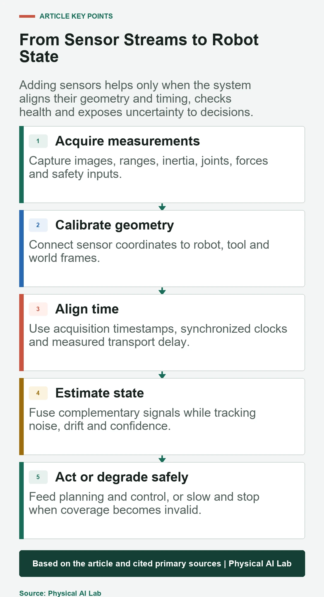
A moving robot sees different states at different moments. If an image, joint angle and force reading have inconsistent timestamps, fusion can create a state that never existed. Hardware triggers, clock synchronization and timestamping near acquisition reduce this error.
Measure transport and processing latency in addition to sampling rate. Buffering may align streams but increases response delay. The right policy depends on task speed: slow inspection tolerates more delay than collision avoidance or dynamic grasping.
Sensor fusion should expose uncertainty and faults
Fusion combines complementary measurements, such as a high-rate IMU with a drift-limiting camera or lidar. Filters, optimization and learned estimators can all be used. The architecture should identify stale, saturated, missing or inconsistent inputs instead of averaging every stream without health checks.
The resulting estimate feeds planning and control, not just a dashboard. A world model may use the fused state to predict outcomes. Safety logic can slow or stop when coverage, confidence or sensor agreement falls below a validated threshold.
Select sensors through task-level testing
Build a measurement budget for each task decision: required range, accuracy, field of view, update rate, latency and allowed failure probability. Test representative surfaces, lighting, vibration, temperature and occlusion. Include dirty lenses, blocked returns and disconnected devices in fault tests.
Compare task success with individual sensors removed or degraded. This reveals redundancy and hidden dependencies. Record raw data where practical so algorithms can be replayed, but manage bandwidth, privacy and retention. The best suite is the smallest one that meets coverage and safety with diagnosable margin.
- Define the decision each sensor supports.
- Measure range, accuracy, rate and latency.
- Calibrate space and time together.
- Test material and environmental edge cases.
- Design fault detection and a safe degraded mode.
Frequently asked questions
What sensor does every robot need?
There is no universal set. Most robots need internal position feedback, while external sensors depend on navigation, manipulation, interaction and safety requirements.
Is lidar better than a depth camera?
Neither is universally better. Lidar often offers robust range and wider distance, while depth cameras provide dense local geometry. Environment, materials, field of view and cost determine the choice.
Why combine an IMU with a camera or lidar?
The IMU provides high-rate motion information but drifts when integrated. Vision or lidar supplies environmental references that can correct longer-term drift.
Are force and tactile sensors the same?
No. A wrist force-torque sensor measures net loads at one location. Tactile sensors measure contact distribution closer to the surface and can reveal local pressure or slip.
How often should robot sensors be calibrated?
Calibrate at commissioning and after mechanical changes or impacts, then monitor health continuously. The interval depends on mounting stability, environment and task tolerance.
Sensor Selection Note
Sensor specifications, firmware and supported interfaces change. Verify current manufacturer documentation and test the complete sensor-to-decision chain under the robot's real materials, lighting, motion and fault conditions.