In ros2_control, a hardware interface exposes named state and command interfaces; Resource Manager owns those resources, and Controller Manager runs controllers through the read-update-write loop. Choose System, Actuator or Sensor according to hardware topology, not by class-name preference.
This architecture makes controllers reusable, but it does not make a driver deterministic or a robot safe. Interface names, units, lifecycle, ownership, update timing and failure behavior must all match the real device. A loaded plugin is only the beginning of commissioning.
Use this guide with the ROS 2 real-time control guide and joint control-mode guide. Follow the documentation branch that matches the deployed ROS and ros2_control versions, and use the ROS 2 executor and callback-group guide when scheduling rather than hardware ownership is the bottleneck.
How ros2_control connects hardware to controllers
Controllers should calculate commands from references and measured state without embedding vendor protocol details. Hardware components should translate between the physical device and agreed interfaces without deciding the robot task. Resource Manager and Controller Manager connect these sides and enforce lifecycle and claims.
Document which layer owns scaling, offsets, saturation, watchdogs, fault reset and mode transitions. If two layers both apply a limit or conversion, behavior can differ between simulation and hardware. If neither owns it, an apparently valid command may reach the device unchecked.
Follow the read-update-write loop
A typical control cycle reads hardware state, updates active controllers and writes resulting commands. The measured period should be passed consistently so controllers can handle timing. State used by the update corresponds to a physical sampling time that may precede the software call.
Instrument read, controller update and write separately. Record worst observed duration, jitter, overruns and data age. The ros2_control architecture documentation explains the roles; the installed driver and bus determine actual timing.
| Layer | Owns | Must expose | Typical failure |
|---|---|---|---|
| Hardware component | Device communication | State and command interfaces | Timeout or unit error |
| Resource Manager | Resources and lifecycle | Available and claimed interfaces | Name or state mismatch |
| Controller Manager | Controller lifecycle and loop | Controller state and timing | Activation or overrun |
| Controller | Control law | Required interfaces and references | Invalid mode or saturation |
| Robot application | Goals and operating state | Validity and fallback | Unsafe transition |
State and command interfaces have different authority
State interfaces carry measured or derived values such as position, velocity, effort, temperature or device status. Command interfaces carry requested values such as position, velocity, effort or custom device commands. Matching names alone does not establish units, sign, range or update semantics.
Create an interface contract for each joint and sensor. Include unit, direction, wrap behavior, valid range, source timestamp, unavailable-value behavior and physical owner. Verify values at rest and during a small known motion before enabling closed-loop control.
The URDF ros2_control tag is an executable contract
The robot description identifies hardware component type, plugin, parameters, joints, sensors and interfaces. Joint names in the ros2_control block must align with the robot model expected by controllers. A spelling difference can leave a controller loaded but unable to claim its resources.
Treat xacro-generated output as the configuration under test. Archive the rendered URDF and parameter files, not only the source macros. Validate duplicate names, plugin class, interface set, limits and initial values before starting real actuators.
Choose System, Actuator or Sensor from hardware topology
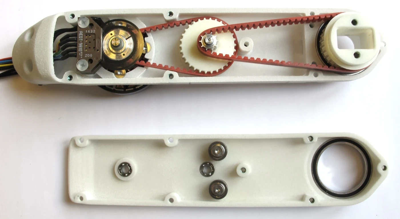
A System component commonly represents complex multi-degree-of-freedom hardware that shares communication or transmissions. An Actuator represents a simpler commandable device, often one degree of freedom. A Sensor exposes read-only device state. The choice affects organization, not the physical capability by itself.
The current hardware-interface type documentation describes these categories and URDF structure. Match the branch to deployment because APIs and features evolve. Do not split one bus into plugins that compete for the same connection without a defined coordinator.
| Component type | Typical hardware | Read | Write | Design question |
|---|---|---|---|---|
| System | Robot arm or coupled hand | Multiple states | Multiple commands | Is communication shared? |
| Actuator | Independent motor or valve | Optional or local state | Device command | Is ownership modular? |
| Sensor | IMU or force sensor | Sensor state | None | Who timestamps and validates? |
| Mock component | Simulation or integration test | Generated state | Accepted command | Which failures are modeled? |
| Custom topology | Vendor-specific device set | Contract dependent | Contract dependent | How are shared faults contained? |
Lifecycle separates loading from safe operation
Hardware and controllers pass through lifecycle states. Loading proves that code and configuration can be instantiated; activation grants operational participation. Define what configure, activate, deactivate, cleanup and error mean for the physical device, including brakes, drive enable and retained commands.
Test failed configuration, partial hardware availability and reactivation after an error. A controller should not become active against stale state or an incompatible drive mode. Make the HMI show hardware state, controller state and robot operating state separately.
Command interfaces require exclusive claims
Controllers claim the command interfaces they require. Two independent controllers generally cannot own the same command resource simultaneously. Multiple controllers can coexist when their claims do not conflict or when a supported chain explicitly defines how references flow.
Before switching, inspect required and claimed interfaces. Define strictness, timeout and fallback behavior for the transition. A position controller and effort controller may require a physical drive-mode change beyond a software claim; coordinate that change with limits and verified state.
Update rate is not a timing guarantee
The configured update rate is a target schedule. Kernel scheduling, executor work, memory faults, driver blocking, bus delay and slow controllers determine whether deadlines are met. Average frequency can look correct while occasional long cycles destabilize a fast joint.
Measure period distribution and each loop segment under full logging, network and sensor load. Separate non-real-time services and parameter work from the control path. Use the real-time guide to design memory, scheduling and data-exchange evidence.
Keep hardware I/O bounded and observable
A read or write call should have a documented upper bound and failure result. Network drivers need deadlines, sequence handling and device-state checks. Returning old state as if it were fresh can be more dangerous than reporting an error because controllers continue from a false present.
Expose communication age, packet loss, drive faults, saturation and temperature through appropriate state or diagnostics without blocking the loop. Decide whether one failed joint stops a component or permits degraded operation, and make that choice consistent with the system safety analysis.
Debug names, lifecycle, claims and timing in order
When a robot does not move, first compare rendered URDF names with listed hardware interfaces. Then inspect hardware lifecycle, controller type and state, required interfaces and actual claims. Only after ownership is correct should gain tuning or trajectory behavior become the primary suspect.
The Controller Manager documentation and ROS 2 control CLI expose controller and hardware state. Save their output with logs so an intermittent activation or conflict can be reconstructed.
Commission from mock hardware to loaded motion
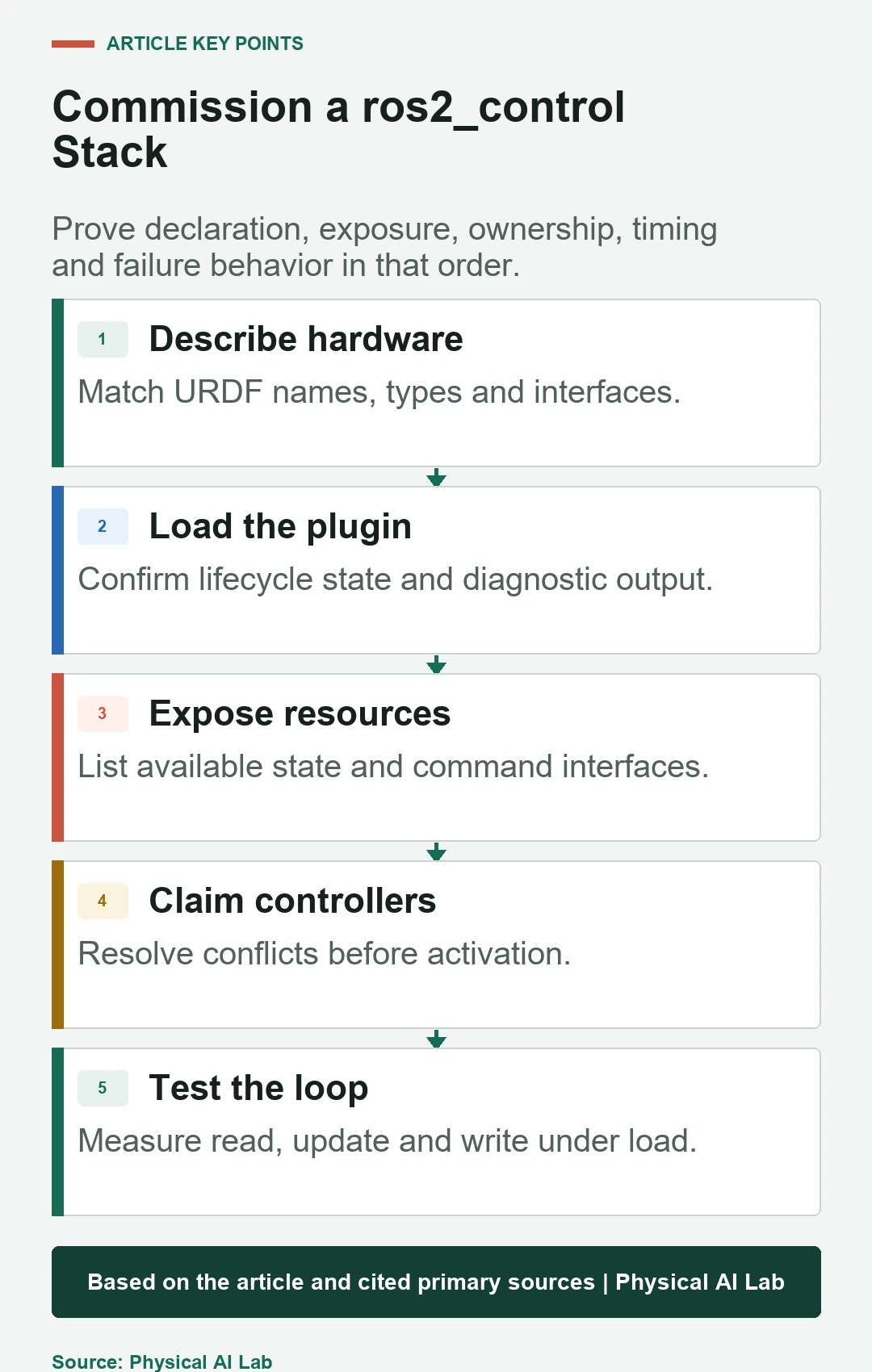
Start with schema and plugin tests, then mock components or a simulator, device communication without actuation, low-power single-joint movement and finally coordinated motion under representative load. Each stage should introduce a defined failure and verify the expected state transition.
Simulation can test names, claims and controller logic but not bus jitter, encoder wiring, brakes, thermal limits or real fault codes. Preserve the same interface contract across stages and list every behavior that the mock does not reproduce.
Create separate integration and control acceptance gates
Integration acceptance verifies component loading, lifecycle, interface values, claims, switching, timeouts, restart and diagnostics. Control acceptance verifies tracking, disturbance response, saturation, limits and stability over payload and temperature. Separating them prevents a control symptom from hiding a broken interface.
Archive the exact ROS distribution, ros2_control packages, hardware firmware, URDF, parameters and test results. Use a compact commissioning checklist for every release.
- Verify rendered names, units and signs.
- Inspect hardware and controller lifecycle states.
- Confirm required and claimed interfaces.
- Measure read-update-write timing under load.
- Inject communication, restart and mode-switch failures.
Frequently asked questions
Is ros2_control a motor driver?
No. It is a framework that connects controller logic to hardware plugins; the plugin or a lower library implements device communication.
What is the difference between state and command interfaces?
State interfaces expose measured or derived values, while command interfaces accept requested values and therefore require controlled ownership.
Why is a controller loaded but the robot does not move?
The controller may be inactive, unable to claim an interface, connected to mismatched names or facing an inactive or faulted hardware component.
Can several controllers run at once?
Yes when their interface claims are compatible or an explicit chaining design supports them. Conflicting command ownership must be resolved.
Does update_rate make the loop real time?
No. It sets a target rate; bounded scheduling, code paths, drivers, memory and hardware communication must be measured separately.
ros2_control Integration Boundary
ros2_control provides software architecture and lifecycle mechanisms. It does not by itself guarantee real-time performance, controller stability, hardware correctness or functional safety.