Humanoid balance is dynamic. The center of mass can be vertically projected inside the feet while momentum still carries the robot beyond recoverable contact. ZMP, capture point and model predictive control describe different parts of this problem: feasible contact action, stopping location and constrained future decisions.
A practical controller combines state and contact estimation with ankle, hip and stepping strategies. The available response shrinks with friction, foot geometry, joint torque, speed, travel, temperature, computation delay and reachable footholds. No indicator guarantees recovery from every disturbance.
Read this with the whole-body control guide and humanoid power guide. A balance claim needs repeated physical trials, disclosed support equipment and a defined disturbance envelope.
Separate balance state, control action and recovery choice
State estimation describes base pose, velocity, center of mass, momentum and contacts. Contact mechanics limits the forces and moments the feet can apply. The controller then chooses ankle torque, angular momentum, a step or a protective action. Mixing these layers can make one plotted variable look more authoritative than it is.
Define the task and failure boundary first: quiet standing, walking, turning, carrying, manipulation or recovery from a known push. State whether hand contact, stepping, a tether or environmental support is allowed. A controller successful under one contract may fail under another without contradiction.

Static center-of-mass projection is not enough
For a stationary rigid body, a center-of-mass projection inside the support polygon is a useful intuition. During motion, velocity and angular momentum matter. A humanoid can have a geometrically favorable position but enough momentum to cross the available support before it can dissipate energy.
Track center-of-mass position and velocity, centroidal momentum, foot wrench and contact state together. Estimate uncertainty and delay. A visually upright pose is not necessarily recoverable, while a tilted pose may be recoverable through a planned step or controlled hand contact.
| Concept | Primary question | Useful decision | Important limit |
|---|---|---|---|
| Support polygon | Where can contact act? | Geometric support region | Assumes valid contacts |
| ZMP | Where is resultant contact moment represented? | Feasible ankle/contact action | Model and contact assumptions |
| Capture point | Where must support move to stop? | Step or no-step decision | Simplified dynamics |
| MPC | Which future actions satisfy constraints? | Sequence and timing | Model, horizon and compute |
| Recovery map | What disturbances were survived? | Evidence boundary | Test coverage |
ZMP describes a feasible contact-moment condition
The zero moment point is the point on the support surface where the horizontal components of the net moment are zero under the adopted model. Keeping the planned ZMP within a feasible support region helps maintain contact without requiring an impossible ankle moment.
ZMP is not a universal stability certificate. Uneven terrain, multiple non-coplanar contacts, foot rotation, slipping, angular momentum and model mismatch complicate the interpretation. Use measured foot wrenches and contact diagnostics to determine whether the assumed support remains valid.
Capture point links velocity to a stopping foothold
Under a linear inverted-pendulum approximation, the capture point indicates where support would need to be placed so the system can come to rest without continued stepping. It combines center-of-mass position and velocity, so it reveals risk that a position-only support test misses.
When the capture point leaves the current feasible support, a step may be required, but the real robot must also reach that foothold in time. Hip motion, variable height, angular momentum and multiple steps can expand behavior beyond the simplest model.
Ankle, hip and step strategies cover different ranges
Ankle strategy changes the center of pressure through foot torque and works while friction and foot-moment limits have margin. Hip strategy changes angular momentum and can redirect body motion, but it consumes joint range, torque and time. Stepping creates a new support region at the cost of swing-foot timing and terrain dependence.
A coordinated controller should switch or blend strategies from predicted feasibility, not from one hard threshold without hysteresis. model-predictive capture-point research demonstrates one framework integrating ankle, hip and stepping strategies, but its results do not automatically transfer to every robot.
| Strategy | Main resource | Best suited to | Failure boundary |
|---|---|---|---|
| Ankle | Foot moment and friction | Small disturbances | ZMP or friction limit |
| Hip | Angular momentum and joint motion | Moderate fast recovery | Joint and momentum saturation |
| Single step | Reachable foothold and swing time | Larger disturbance | Late or unreachable placement |
| Multiple steps | Future support sequence | Sustained momentum | Space and planning horizon |
| Protective action | Fall management and shutdown | Unrecoverable state | Impact and environment |
MPC chooses a future sequence under constraints
Model predictive control repeatedly predicts future motion over a finite horizon, optimizes actions and applies the first part before solving again. It can coordinate ZMP, foot placement, momentum and timing while respecting selected kinematic, dynamic and contact constraints.
The prediction is only as useful as the model, state, contact schedule, horizon, cost and solver completion. A longer horizon can see further but costs computation and remains finite. Define what happens when the optimization is infeasible, late or numerically suspect.
State and contact estimation set the real boundary
An IMU observes angular motion and specific force, joint encoders describe configuration, and foot sensors provide contact evidence. Each has bias, noise, saturation and delay. A falsely declared stance foot can cause the controller to command forces through a contact that no longer exists.
Validate estimator behavior during foot impact, slip, push, sensor dropout and floor compliance. Track innovation, contact probability and time alignment. The sensor-fusion guide explains why synchronized uncertainty matters more than simply adding more sensors.
Actuator and power limits shrink recovery authority
Joint torque, speed and travel limits determine how quickly ankle and hip strategies can redirect momentum. Thermal derating, battery voltage sag and drive-current limits can reduce available authority during a long test sequence even when the same algorithm recovered from the first push.
Include commanded and measured torque, saturation flags, bus voltage, temperature and control delay in the recovery log. Test with realistic payload and arm posture because carried mass changes the center of mass, inertia and reachable step set.
A recovery state machine handles the boundaries
Optimization should sit inside an operating state machine that distinguishes nominal motion, no-step recovery, stepping recovery, controlled descent and protective shutdown. Entry and exit conditions need uncertainty margins and hysteresis so noisy estimates do not make the robot switch strategies repeatedly.
Define which planner owns the swing foot, arms and contacts during recovery. Cancel or modify manipulation goals explicitly. If a fall becomes unavoidable, protect people, reduce impact where possible and isolate energy according to the validated safety design.
Test a disturbance matrix rather than one push
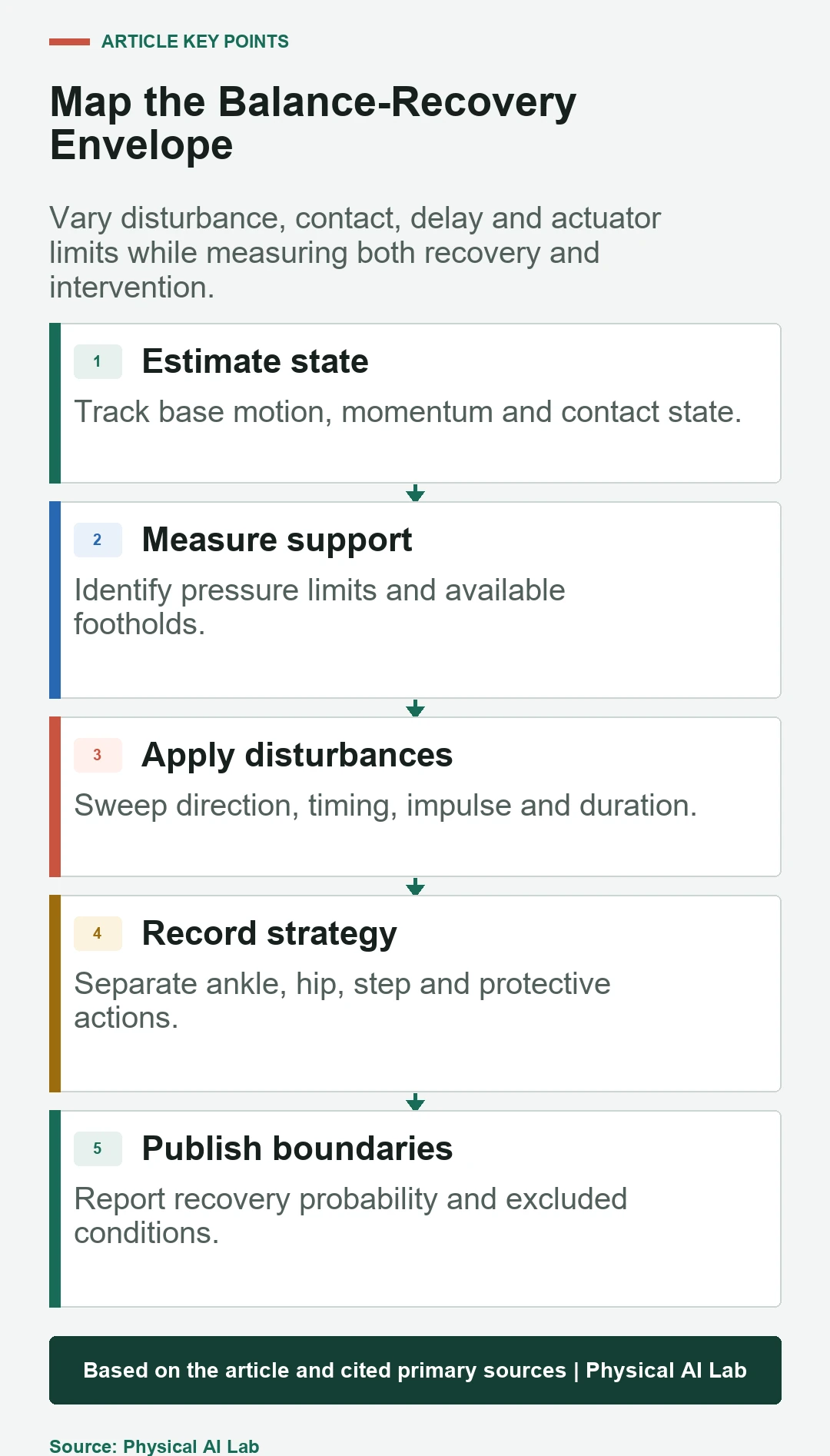
Vary direction, application point, impulse, duration and phase of the gait. Repeat on different friction, compliance and slope conditions and at several battery and thermal states. Use an instrumented pusher, pendulum or force measurement where repeatability matters.
Report total trials, recoveries, steps, falls, protective interventions and excluded runs. push-recovery research using MPC and capture point provides a concrete research example; operational validation still requires the target robot and environment.
Publish a balance-recovery map
A useful result maps disturbance magnitude and direction against pose, gait phase, permitted strategies and outcome. Add recovery time, maximum step displacement, joint saturation, foot slip and solver misses. This shows where performance degrades instead of reducing balance to a pass or fail label.
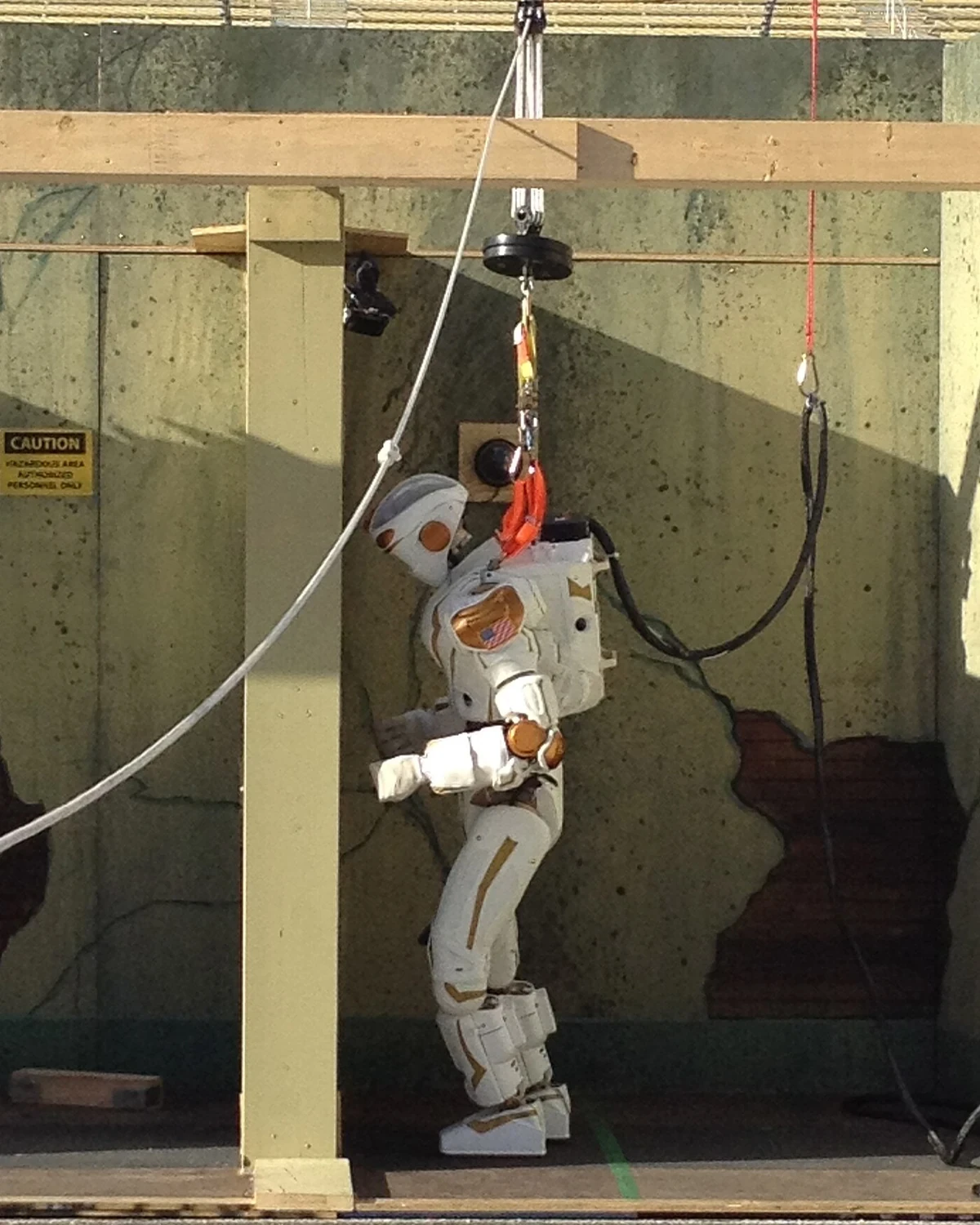
Separate untethered trials from trials using an overhead rig, boom, cable or external power. The equipment is often essential for development, but it can constrain motion, catch a fall early or change observable consequences. Disclose its mechanical role.
Connect balance performance to operational safety
Balance control is not a protective safety function unless it has been developed and validated within the applicable safety architecture. A humanoid that usually recovers can still fall, eject an object or step into a person. Define exclusion zones, spotter procedure and emergency response for testing.
Use an evidence checklist that preserves model assumptions, software version and test conditions.
- Define allowed contacts and recovery strategies.
- Log state, contact, solver and actuator evidence together.
- Sweep disturbance, phase, terrain and delay.
- Report repeated outcomes and support equipment.
- Specify the safe response outside the recovery map.
Frequently asked questions
Does ZMP inside the foot guarantee the humanoid will not fall?
No. Momentum, slipping, foot rotation, model error and actuator limits can still make the state unrecoverable.
Does a capture point outside support always require a step?
Not always. Hip motion, changing height or other contacts may help, but a step is the direct way to create new support in many cases.
Can MPC recover from every disturbance?
No. Recovery is limited by the model, contacts, reachable footholds, actuator authority, computation and available space.
Is a faster balance loop always better?
Only when sensing, computation and actuation remain valid. Faster nominal rate does not help if timestamps, noise or solver overruns dominate.
How should push recovery be compared?
Compare a disclosed disturbance matrix, trial count, recovery probability, step and saturation metrics, terrain, payload and support equipment.
Humanoid Balance Evidence Boundary
Humanoid balance results are platform and condition specific. Models and indicators do not guarantee recovery; test with controlled risk, disclosed support equipment and a defined protective response.