Matching mechanical references do not guarantee that a tool interface connects the intended utility channels. In our Blender experiment, the aligned pose mapped master port A to tool port A and B to B. With the tool posed at 180 degrees in a separate assembly, the same authored pilot and four mounting-hole positions still matched, but the measured aperture map became A to B and B to A.
This was an AI-operated static-geometry experiment in Blender 5.2.2 LTS. It used a generic unkeyed interface with open through-bores. It did not reproduce a commercial tool changer or test fluid flow, electrical continuity, seals, locks, forces, robot motion or hardware safety.
The half-turn preserved the references and exchanged the ports
We created two separate static cells. The upper-left cell held the tool at 0 degrees; the lower-right cell held it at 180 degrees. These are two evaluated poses, not a continuous rotation.
Both cells used the same circular pilot, symmetric mounting pattern and two off-axis utility passages. The master ports kept the IDs M_A and M_B; the tool ports kept T_A and T_B. The declared contract was A-to-A and B-to-B.
| Tool orientation | Measured positive-area aperture pairs | Overlap area | Declared identity contract |
|---|---|---|---|
| 0 degrees | M_A → T_A; M_B → T_B |
About 49.94 mm² each | Matches |
| 180 degrees | M_A → T_B; M_B → T_A |
About 49.94 mm² each | Does not match |
Every other master-to-tool pairing had zero overlap area. The intended through-bores remained unobstructed in both cells.
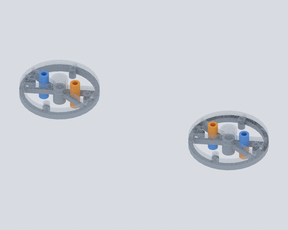
The mechanical reference checks did not distinguish the two poses. All four unlabelled mounting-hole positions matched in each cell. The finite pilot clearance was about 0.199 mm, and the male and female pilot extents overlapped axially by about 5.000 mm. Those measurements establish matching reference geometry and pilot clearance in the authored poses. They do not establish physical insertion, locking strength, manufacturing tolerance or product compatibility.
Keep reference geometry, port pairing and function separate
A ported interface has at least four questions, and passing one does not answer the others.
| Check | What it asks | What our experiment established |
|---|---|---|
| Mechanical references | Do the mounting-hole positions match, with clearance around the pilot? | Yes, in both authored static cells |
| Aperture continuation | Which open master and tool polygons have positive overlap at the mating plane? | Like-to-like at 0 degrees; exchanged at 180 degrees |
| Channel identity | Does the measured pair map match the declared A-to-A and B-to-B contract? | Yes at 0 degrees; no at 180 degrees |
| Actual function | Does the connected circuit carry its intended medium or signal correctly? | Not tested |
This separation matters because a symmetric pilot or bolt pattern can make two poses look equally acceptable. Labels can also look convincing while hiding the actual mating geometry. The reliable sequence is to derive the geometric connection map first and compare persistent channel IDs second. Powered or pressurized testing comes later.
The distinction is similar to a frame problem: rotating the tool changes where tool-fixed features land even when the interface origin stays put. The broader robot coordinate-frames guide explains how to keep those part-fixed coordinates explicit.
We measured openings rather than colored circles
Blue and orange made the channels readable in the render, but color was not evidence. We recovered each bore axis and its aperture boundary from the evaluated mesh topology. The opposing boundary polygons were projected into the common mating plane, and every master-to-tool polygon pair was intersected there.
Positive polygon area identified geometric continuation. Zero area meant that pair did not continue through the interface. We also checked that the passage behind each aperture remained open, so a coincident center marker could not stand in for a blocked bore.
The scene contained 64 closed meshes with 4,352 vertices across both static cells. We captured the complete geometry in each independent read. The bores had 32-sided boundaries, so the approximately 49.94 mm² matched area is a polygon measurement, not an exact circular area. Independent checks reconstructed the references and aperture maps rather than trusting labels.
Captured corners were checked against the authored geometry within 4 micrometres; two-solid comparisons allowed 8 micrometres. Positive aperture area had to exceed a coordinate-derived allowance of about 0.201 mm². These are numerical consistency bounds for this digital model, not manufacturing tolerances or hardware accuracy. The schematic support junctions were not tested for structural attachment or load.
One issue was removed before the measured scene was created: the tool-side spokes began 8 mm from the pilot axis and intruded into its 9.2 mm inner-radius cavity. We moved their inner ends to 10 mm from the axis while keeping the master-side starts at 8 mm. That was a correction to our draft model, not a fault discovered in a physical tool changer.
Product documentation still controls the real interface
Zimmer Group describes its energy elements as interfaces for transferring media and electrical connections. The examined WER3000 product page links installation manual DDOC00214/h, English, dated June 22, 2026. That manual distinguishes a fixed robot-side part from a loose tool-side part and makes clear that transferred media and technical data depend on the variant.
Those sources give useful integration context, but they do not say that our generic geometry represents a Zimmer product or that the examined product permits a 180-degree clocked installation. We did not copy its port layout, seal distances or contact assignments.
The end-effector tool safety guide covers the broader questions of tool identity, locking and integration. The narrower lesson here is that a mechanical seat and a utility map need separate acceptance checks.
Check every permitted clocking pose before connecting utilities
For a real interface, start with the manufacturer-approved poses rather than assuming a symmetric-looking pose is allowed. For each permitted pose:
- Verify the mechanical index, pilot, mounting pattern and seating distance.
- Recover each actual aperture at the mating plane and build the master-to-tool continuation table.
- Compare that measured table with the declared pneumatic, vacuum, electrical or signal-channel identities.
- Check variant-specific seals, installation distances and connector assignments in the applicable manual.
- Only then test the actual media or electrical function with the proper hardware procedure.
Our authored half-turn is a deliberately generic counterexample. It shows why “the flange fits” is not enough: at 180 degrees the mechanical references still matched, while both utility identities were exchanged. It does not show leakage, cross-connection under pressure, electrical behavior, latch retention, insertion force, controller response or safe operation.