Speed and separation monitoring, or SSM, is a collaborative robot safety function that reduces robot speed as a person approaches and initiates a protective stop before the required separation is violated. The boundary depends on the complete application, not on a generic radius around the robot.
A defensible design combines human approach, sensing and logic delay, robot reaction and stopping motion, intrusion and measurement uncertainty. It then verifies those inputs under the cell’s worst credible speed, direction, payload, tool extension and environmental conditions.
This guide is educational and does not replace the applicable standard text, local law or a qualified machinery-safety assessment. Pair it with the collaborative-robot safety guide and functional-safety guide.
Define SSM as an application safety function
SSM coordinates detection, safety-related logic, robot speed control and protective stopping for a specific robot application. A collaborative-rated arm does not make any tool, workpiece, layout or programmed motion safe by itself.
Document hazards, operating modes, people who may enter, foreseeable misuse and the safety function required in each state. Keep production optimization separate from the safety claim.

Map every human and robot approach path
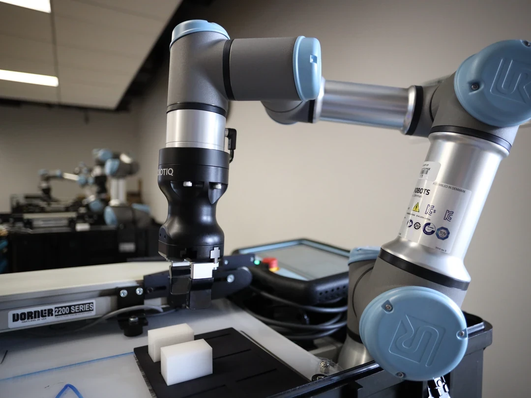
Trace shortcuts, reach-over and reach-around routes, floor-level access, maintenance positions and entry from inside the safeguarded space. Include all moving links, end effectors, cables, workpieces and ejected or suspended loads in the robot envelope.
Use the nearest points of the changing human and machine geometries, not only base-to-person distance. Reassess when fixtures, tools, layout or programmed paths change.
| Distance component | Evidence | Adverse condition | Review trigger |
|---|---|---|---|
| Human approach | Declared applicable value | Fastest relevant path | Access change |
| Detection and logic | Measured safety-chain time | Occlusion or load | Sensor or logic change |
| Robot reaction | Controller trace | Worst speed and direction | Software change |
| Robot stopping | Measured motion | Payload and tool extension | Brake or tool change |
| Uncertainty | Sensor and intrusion allowance | Tolerance stack | Calibration change |
Account for the complete response time
Measure from the physical detection condition through sensing, communication, safety logic, drive reaction and completed stopping behavior. Nominal network or inference latency alone omits important parts of the chain.
Use worst credible and validated response, including jitter and fault behavior. Tie each value to hardware, firmware, configuration, timestamped test and environmental condition.
Measure stopping under adverse robot conditions
Stopping time and distance can vary with speed, direction, pose, payload, center of gravity, tool, extension, brake condition and control settings. Manufacturer information is an input, not a substitute for application verification when the actual cell differs.
Test a matrix that searches for the longest relevant stopping path and repeat enough trials to capture variation. Maintain the measurement method and acceptance rule with the safety file.
Add intrusion and position uncertainty
Protective equipment has detection-zone geometry, resolution, tolerance and possible intrusion before detection. Robot and human position estimates also have calibration, tracking and synchronization error.
Combine allowances conservatively according to the applicable design method. Do not subtract average localization accuracy from a safety distance or assume independent errors without evidence.
Treat occlusion and tracking loss as loss of safety information
When a person becomes occluded, the system does not know that separation increased. Define the safe state for missing detections, degraded confidence, stale tracks, blocked fields of view and sensor disagreement.
Test clothing, carried objects, glare, dust, lighting, crowding and the robot itself as occluders. Detection quality for a general vision model is not automatically a safety-rated protective function.
Design speed zones as safety states
Multiple speed zones can improve productivity, but every state has its own monitored condition, maximum speed, required separation, transition logic and stop behavior. Add hysteresis so noisy distance estimates do not cause rapid speed switching.
Verify the actual commanded and achieved speed after each transition. A display that shows slow mode is not evidence that all relevant robot motion is limited.
Control stop, reset and restart
Define whether boundary crossing causes speed reduction, protective stop or another validated state. After a stop, require valid sensing, sufficient separation, cleared faults and an authorized restart condition that cannot surprise a person inside the cell.
Test someone remaining hidden, re-entering during reset, standing inside a blind zone and restoring communications. The state machine must prevent automatic acceleration from stale clearance.
Use current standards within their scope
The official ISO catalog lists ISO 13855:2024 as the current published edition for positioning and dimensioning specified safeguards relative to human approach. It also lists ISO 10218-2:2025 for industrial robot applications and cells.
The catalog lists ISO/TS 15066:2016 and ISO 13849-1:2023 as published. Determine the applicable editions, transition rules, jurisdiction and Type-C requirements with competent safety professionals rather than relying on this summary.
Connect calculation terms to safety evidence
For each term in the separation calculation, identify sensor channel, logic block, drive response, measurement record, uncertainty source and verification test. Configuration control should make a changed parameter or component visible to the safety review.
Link the calculation to safety-related control-system design and validation evidence. A spreadsheet result without traceable inputs and fault behavior is incomplete.
Validate worst-case closing scenarios
Reproduce adverse human approach and robot motion toward the same boundary, including diagonal routes, maximum extension, payload, warm equipment and sensing delay. Exercise zone transitions, protective stop, occlusion and restart repeatedly.
Measure actual minimum separation and completed stopping, then compare with the approved acceptance rule. Record unsuccessful trials and the conditions that produced them.
| Test layer | Injected condition | Expected response | Evidence |
|---|---|---|---|
| Detection | Occlusion or stale track | Safe state | Timestamped trace |
| Logic | Delay or channel fault | Protective response | Safety log |
| Motion | Worst payload and direction | Within stopping boundary | Position trace |
| Transition | Rapid zone crossing | No unsafe overshoot | Speed trace |
| Restart | Person remains inside | No unexpected motion | State-machine record |
Maintain SSM across cell changes
Recalculate and revalidate after robot, tool, workpiece, payload, program, speed, layout, sensor, firmware, braking, floor marking or access-route changes. Monitor stopping trends and calibration between formal tests.
Close the review with the following checks.
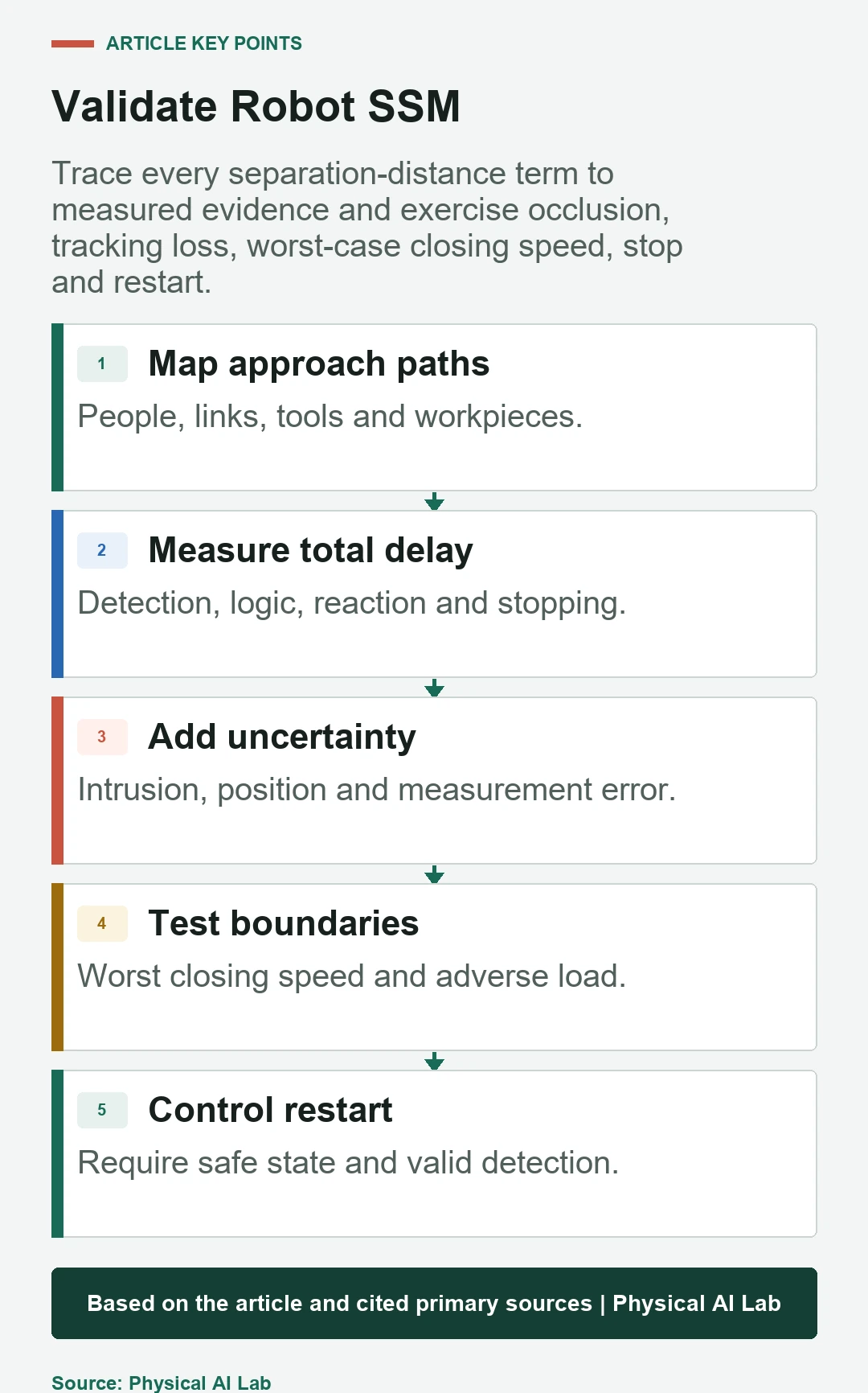
- Map actual human routes and the complete moving envelope.
- Measure the full safety-chain response time.
- Test adverse stopping and uncertainty conditions.
- Treat occlusion and tracking loss as faults.
- Verify stop, reset and restart under the applicable safety process.
Frequently asked questions
Is the SSM protection distance always fixed?
No. It depends on operating state, closing motion, response time, stopping behavior, geometry and uncertainty.
Can I use only the robot manufacturer's stopping time?
Use manufacturer data as applicable input, but verify the complete cell under its actual load, tool, pose and configuration.
Can a general camera person detector serve as the SSM sensor?
Not by default. The protective function requires appropriate safety-related performance, fault behavior and validated coverage.
May the robot accelerate automatically when a person moves away?
Only through a validated state machine with sufficient separation, valid sensing and compliant reset or restart behavior.
Is one commissioning test enough?
No. Revalidation and periodic checks are needed after relevant changes and according to the applicable safety plan.
Measured-Separation and Protective-Stop Boundary
SSM is an application-specific protective function. Use current applicable standards and competent safety engineering to validate sensing, full stopping behavior, uncertainty, faults and restart in the actual robot cell.